
Method and equipment for using route switching equipment

A switching device and routing technology, applied in the network field, can solve problems such as slow CPU operation, easy to be discarded, and affect the speed of protocol convergence on the controller, and achieve the effect of saving CPU resources

Active Publication Date: 2016-03-30
IBM CORP
View PDF6 Cites 8 Cited by
  • Summary
  • Abstract
  • Description
  • Claims
  • Application Information

AI Technical Summary

Problems solved by technology

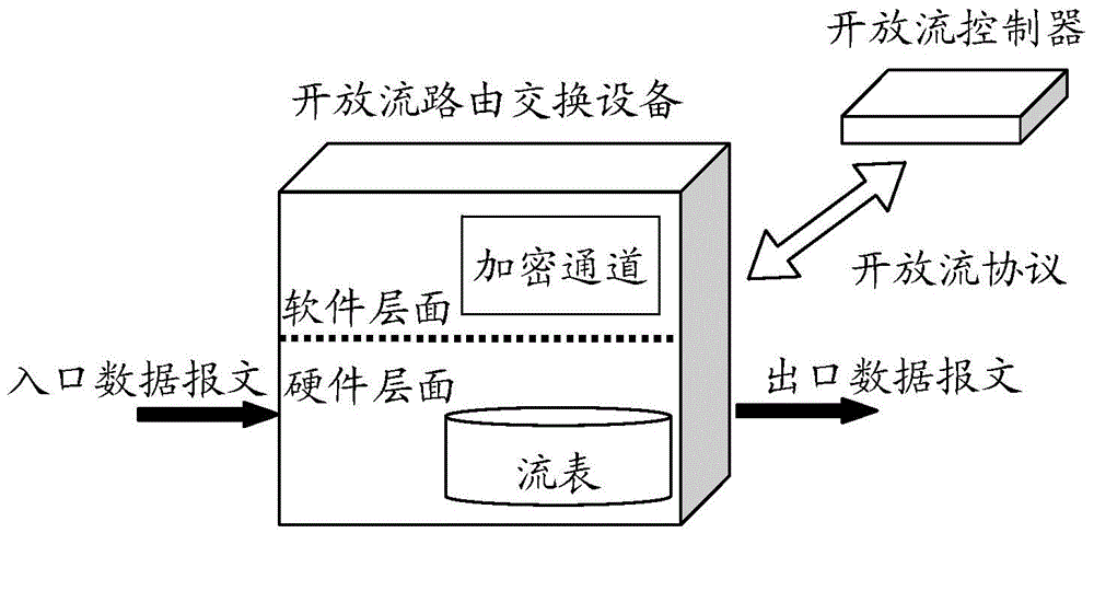
In the existing technical solution, once the routing and switching device re-establishes a connection with the controller, the routing and switching device will return to the open flow mode from the non-independent mode. At this time, the original flow entry has been deleted, and the routing and switching device needs to Waiting for the protocol convergence on the controller to add flow entries. The protocol convergence speed is generally slow. Before that, only the above-mentioned default processing rules exist, and the action of the default processing rules is to send all packets that do not match the flow entries to the controller, and a message sent to the controller will be soft-forwarded by the CPU of the switch. This channel itself is very narrow. There are only megabits per second (Mbps), and more packets on the order of megabits per second will be discarded. As a result, if there are protocol control packets mixed in the data stream, they are easily discarded, affecting the protocol convergence on the controller. speed
Moreover, the processing of packets through soft forwarding by the CPU will occupy a large amount of CPU resources, causing the CPU to run very slowly.
However, a large number of data packets are sent to the controller, which also needs to be calculated, which wastes the resources of the controller and is useless for protocol calculation (the controller performs protocol convergence according to the protocol control message)

Method used


Image

  • Method and equipment for using route switching equipment
  • Method and equipment for using route switching equipment
  • Method and equipment for using route switching equipment

Examples


Embodiment Construction

[0023] Preferred embodiments of the present disclosure will be described in more detail below with reference to the accompanying drawings. Although preferred embodiments of the present disclosure are shown in the drawings, it should be understood that the present disclosure may be embodied in various forms and should not be limited to the embodiments set forth herein. Rather, these embodiments are provided so that this disclosure will be thorough and complete, and will fully convey the scope of the disclosure to those skilled in the art.

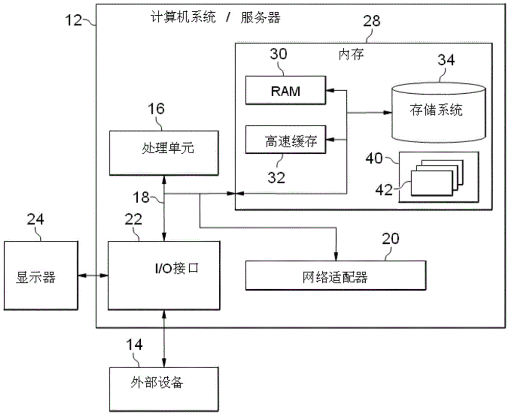
[0024] figure 1 A block diagram of an exemplary computer system / server 12 suitable for use in implementing embodiments of the invention is shown. figure 1 The computer system / server 12 shown is only an example and should not impose any limitation on the functions and scope of use of the embodiments of the present invention.

[0025] Such as figure 1 As shown, computer system / server 12 takes the form of a general purpose computing device. ...


PUM


Abstract

The invention discloses a method and equipment for using route switching equipment, and the method comprises the steps: responding to the switching of the route switching equipment from a conventional mode to an open flow mode, and carrying out the following steps: converting items of a forwarding table of the conventional mode into flow table items of the open flow mode; storing the converted flow table items to be stored in the flow table of the route switching equipment; responding to a received data message, and carrying out the processing of the data message according to the converted flow table items stored in the flow table. The method and equipment can enable the route switching equipment to be switched to the open flow mode from the conventional mode, and save the CPU resources of the route switching equipment.

Description

technical field [0001] The present invention relates to network technology, more specifically, to a method and device for routing and switching equipment. Background technique [0002] A routing and switching device supporting the OpenFlow protocol can work in an OpenFlow mode or a traditional mode according to its configuration and its connection status with the controller. The traditional mode includes a standalone mode (standalone mode) and a non-independent mode (failstandalone mode). In the non-independent mode, the routing and switching device supporting the OpenFlow protocol has been activated in the OpenFlow mode, but has lost connection with the controller. According to the OpenFlow protocol, a commonly used method to deal with disconnection is: all flows The entry will be deleted, and the traditional forwarding function of the routing and switching device will be enabled, and forwarding will be performed according to the traditional forwarding table. Table 1 show...

Claims


Application Information

Patent Timeline
Patent Type & Authority Applications(China)
IPC IPC(8): H04L12/741H04L12/771H04L45/02H04L45/74H04L45/60
CPCH04L49/70H04L49/35H04L45/38H04L45/036H04L45/02
Inventor 杨亮宋益波李源何京
Owner IBM CORP
Learn More