
A video quality monitoring method, device and CDN system

A video quality and monitoring device technology, applied in image communication, selective content distribution, electrical components, etc., can solve the problems of non-reflection, high complexity of video quality monitoring and fault location, failure to reflect global KPIs, etc. The effect of fault location and video quality monitoring

Active Publication Date: 2019-04-05
CHINA TELECOM CORP LTD
View PDF4 Cites 0 Cited by
  • Summary
  • Abstract
  • Description
  • Claims
  • Application Information

AI Technical Summary

Problems solved by technology

With the standardization of China Telecom's CDN network transmission interface, the CDN bearer network is increasingly popularized by the joint networking of equipment from multiple manufacturers. The upper and lower nodes of the CDN are composed of different manufacturers. The complexity of video quality monitoring and fault location is higher. The existing single interface Monitoring is difficult to analyze global quality data and fault location
The existing video quality monitoring technology generally adopts the independent monitoring of CDN single interface, which has the following problems: (1) It can only reflect the unilateral video KPI output by the server, but fails to reflect the global KPI, such as the delay caused by the server, etc. ;(2) Only the value of the video quality KPI of the interface can be monitored, and the network element node and position causing the KPI abnormality cannot be located
For example, taking the monitoring of the user-side interface (S interface) of the edge server as an example, only the KPIs (such as MLR, DF, and MOS values) output by the server are monitored, but the global KPI parameters, such as the delay caused by the video server, are not reflected. , hit rate, etc., and it cannot reflect whether the cause of the KPI abnormality is caused by the edge server or the upper-level device

Method used


Image

  • A video quality monitoring method, device and CDN system
  • A video quality monitoring method, device and CDN system
  • A video quality monitoring method, device and CDN system

Examples


Embodiment Construction

[0024] The present invention will be described more fully hereinafter with reference to the accompanying drawings, in which exemplary embodiments of the invention are illustrated. The following will clearly and completely describe the technical solutions in the embodiments of the present invention with reference to the accompanying drawings in the embodiments of the present invention. Obviously, the described embodiments are only some, not all, embodiments of the present invention. Based on the embodiments of the present invention, all other embodiments obtained by persons of ordinary skill in the art without making creative efforts belong to the protection scope of the present invention. The technical solution of the present invention will be described in various aspects below in conjunction with various figures and embodiments.

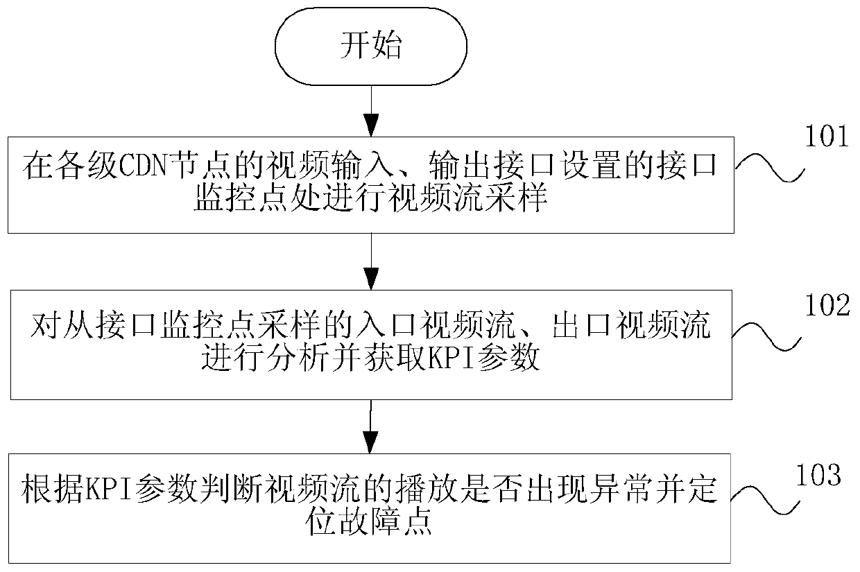
[0025] figure 1 It is a flowchart of an embodiment of the method for monitoring video quality according to the present invention, such as figure ...


PUM


Abstract

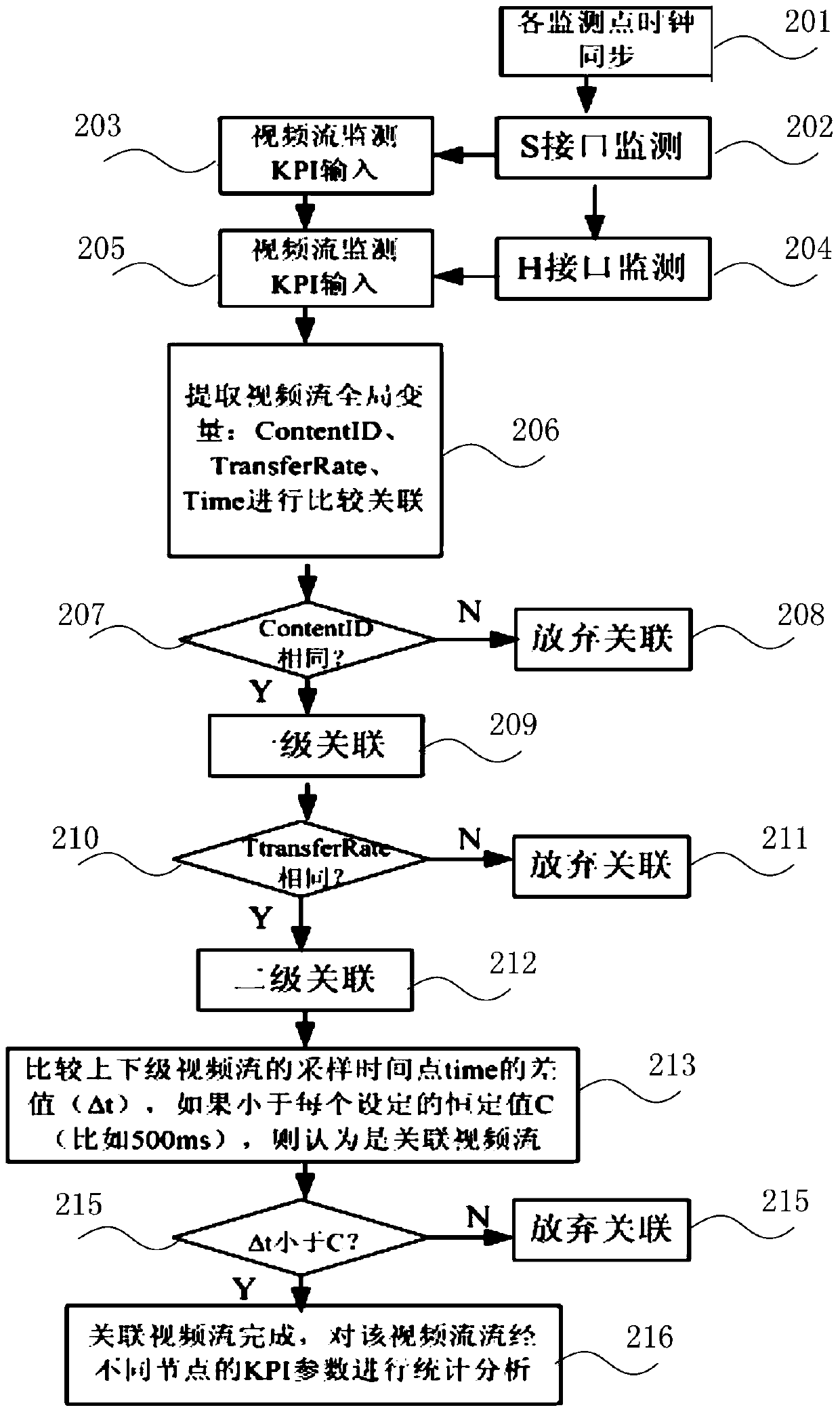
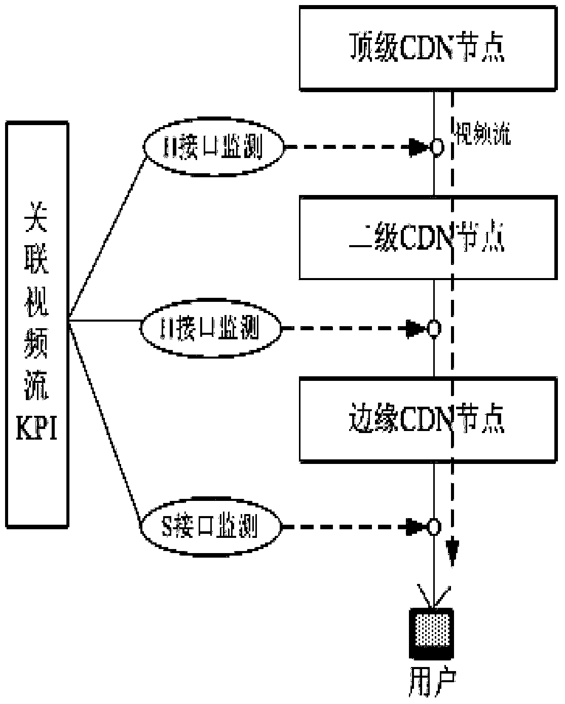
The invention discloses a video quality monitoring method, a video quality monitoring device and a CDN system. The video quality monitoring method comprises the steps of: carrying out video stream sampling at interface monitoring points arranged at video input and output interfaces of CDN nodes at different levels; analyzing inlet video streams and outlet video streams sampled from the interface monitoring points and acquiring KPI parameters; and judging whether the playing of the video streams is abnormal according to the KPI parameters, and positioning a fault point. The video quality monitoring method, the video quality monitoring device and the CDN system can conduct whole-course tracking and monitoring of video streams during CDN video quality monitoring, are used for carrying out double monitoring on upper and lower level interfaces of the CDN nodes and associating the corresponding video streams, achieves linkage analysis of inlet video stream KPI and outlet video stream KPI through the KPI monitoring on the inlet video streams and outlet video streams, reflect video quality overall KPI parameters of the upper and lower level nodes objectively, can position the fault point causing the KPI abnormity, and achieve video quality monitoring and fault positioning.

Description

technical field [0001] The invention relates to the technical field of video-on-demand, in particular to a video quality monitoring method, device and CDN system. Background technique [0002] IPTV is the use of computer or set-top box + TV to complete the functions of receiving video-on-demand programs, video broadcasting and surfing the Internet. It is currently developing very rapidly. With the standardization of China Telecom's CDN network transmission interface, the CDN bearer network is increasingly popularized by the joint networking of equipment from multiple manufacturers. The upper and lower nodes of the CDN are composed of different manufacturers. The complexity of video quality monitoring and fault location is higher. The existing single interface It is difficult to analyze global quality data and locate fault points in monitoring. The existing video quality monitoring technology generally adopts the independent monitoring of CDN single interface, which has the ...

Claims


Application Information

Patent Timeline
Patent Type & Authority Patents(China)
IPC IPC(8): H04N21/24H04N21/647
Inventor 薛沛林梁洁庄一嵘杨柳
Owner CHINA TELECOM CORP LTD
Learn More