rotation transfer device

A rotation transmission device and relative rotation technology, applied in non-mechanical drive clutches, one-way clutches, magnetic drive clutches, etc., can solve the problems of reduced design freedom, unstable magnetic attraction, large axial gap deviation, etc. The effect of improving the degree of freedom, preventing unstable adsorption, and preventing leakage

Active Publication Date: 2018-01-19
NTN CORP
View PDF8 Cites 0 Cited by
  • Summary
  • Abstract
  • Description
  • Claims
  • Application Information

AI Technical Summary

Problems solved by technology

In this case, if the armature does not attract, there will be a problem. Therefore, it is necessary to install a large-scale electromagnet with a large capacity or increase the input voltage to reduce the design freedom of this part. There is still room for improving the design freedom. Aspects that can be improved
[0009] In addition, the bearing is brought into contact with the axial end surface of the rotor fitting shaft portion formed on the input shaft, so that the input shaft is rotatably supported with respect to the electromagnet and the axial position of the electromagnet is restricted. On the other hand, the rotor It abuts against the flange provided on the input shaft to limit the axial position of the rotor, and manages the axial gap formed between the rotor and the opposing part of the electromagnet. The management of the axial gap is indirectly managed through the input shaft, so the shaft The deviation to the gap is large, and the magnetic attraction force applied to the armature tends to be unstable

Method used


Image

  • rotation transfer device
  • rotation transfer device
  • rotation transfer device

Examples


Embodiment Construction

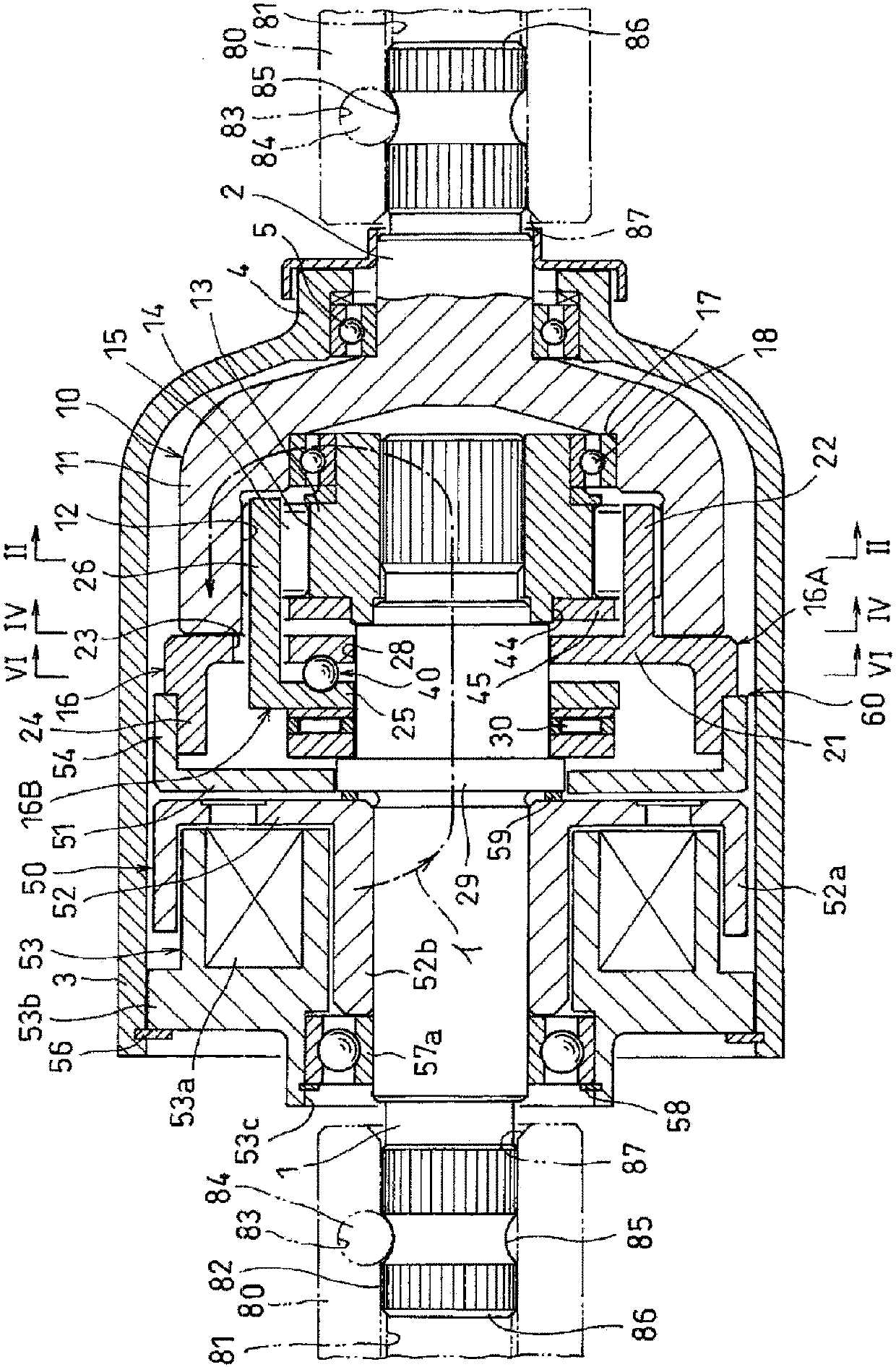
[0032] Hereinafter, embodiments of the present invention will be described with reference to the drawings. figure 1 An embodiment of the rotation transmission device of the present invention is shown. As shown in the figure, the rotation transmission device is composed of an input shaft 1, an output shaft 2 arranged coaxially with the input shaft 1, a housing 3 as a stationary part covering the shaft ends of the two shafts, assembled in the housing 3, and The two-way clutch 10 for transmitting and blocking the rotation from the input shaft 1 to the output shaft 2 , and the electromagnetic clutch 50 for controlling the engagement and release of the two-way clutch 10 are constituted.

[0033] The casing 3 has a cylindrical shape, and a small-diameter bearing tube 4 is provided at one end thereof, and the output shaft 2 is rotatably supported by a bearing 5 incorporated in the bearing tube 4 .

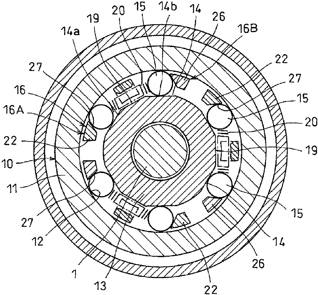
[0034] Such as figure 1 as well as figure 2As shown, the two-way clutch 10 is pro...


PUM


Abstract

To provide a rotation transmission device capable of suppressing magnetic leakage from an armature to a control holder and enabling a two-way clutch to function with high precision and reliability. A restricting mechanism (60) is provided to restrict the connecting cylinder of the armature (51) in a state where a gap is formed between the back surface of the armature (51) adsorbed by the rotor (52) and the end surface of the cylinder (24). (54) The relative fitting amount with the barrel (24) prevents the magnetism from the back of the armature (51) toward the end face of the barrel (24) when the electromagnet (53) is energized to attract the armature (51). leakage.

Description

technical field [0001] The present invention relates to a rotation transmission device for switching between rotation transmission and cutoff. Background technique [0002] As a rotation transmission device that transmits and cuts rotation from a drive shaft to a driven shaft, a device having a two-way clutch and controlling engagement and disengagement of the two-way clutch by an electromagnetic clutch is conventionally known. [0003] The following Patent Document 1 describes a rotation transmission device that controls the engagement and release of a two-way clutch by an electromagnetic clutch. In the above-mentioned two-way clutch, a control cage and a rotation cage are connected between an outer ring and an inner ring assembled inside it. The pillars formed on each cage are assembled in such a way that they are arranged alternately in the circumferential direction, a pair of opposing rollers are assembled into the recesses formed between the adjacent pillars, and the el...

Claims


Application Information

Patent Timeline
Patent Type & Authority Patents(China)
IPC IPC(8): F16D27/112F16D41/06F16D41/08
CPCF16D27/112F16D2023/123F16D41/088F16D27/108
Inventor 北山直嗣笹沼恭兵福成真理名斋藤隆英佐藤光司川合正浩
Owner NTN CORP
Why Eureka
Try Eureka