Glue filling mechanisms and glue filling equipment

A technology of filling equipment and glue, which is applied in the direction of coating, liquid coating device on the surface, etc., can solve the problems of low efficiency and unstable quality of light receiving and emitting components, and ensure product consistency and work efficiency High, stable quality results

Active Publication Date: 2016-04-06
APAT OPTOELECTRONICS COMPONENTS
View PDF10 Cites 4 Cited by
  • Summary
  • Abstract
  • Description
  • Claims
  • Application Information

AI Technical Summary

Problems solved by technology

[0003] The purpose of the present invention is to provide a glue filling mechanism, aiming to solve the technical problems of low efficiency and unstable quality of gluing light receiving and emitting components in the prior art

Method used


Image

  • Glue filling mechanisms and glue filling equipment
  • Glue filling mechanisms and glue filling equipment
  • Glue filling mechanisms and glue filling equipment

Examples


Embodiment Construction

[0046] In order to make the object, technical solution and advantages of the present invention clearer, the present invention will be further described in detail below in conjunction with the accompanying drawings and embodiments. It should be understood that the specific embodiments described here are only used to explain the present invention, not to limit the present invention.

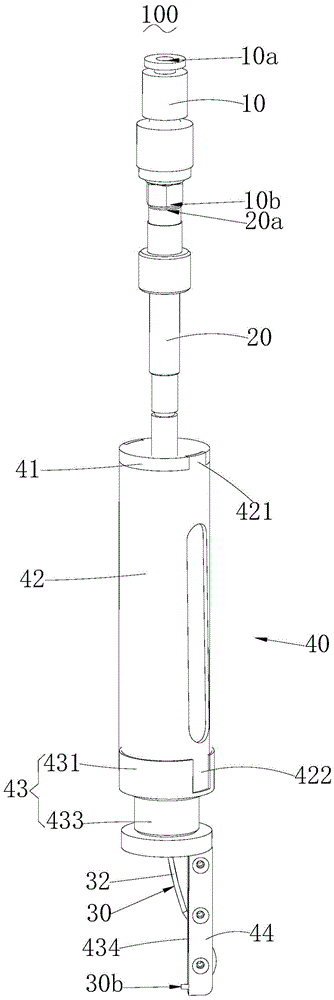
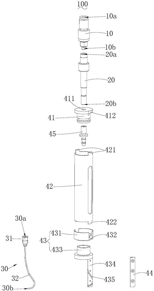
[0047] see Figure 2 to Figure 4 , the glue filling mechanism 100 provided by the embodiment of the present invention includes:

[0048] A rotary joint 10, the rotary joint 10 has a first input end 10a for the glue to enter and a first output end 10b communicated with the first input end 10a;

[0049] A hollow shaft 20, the hollow shaft 20 has a second input end 20a connected to the first output end 10b and a second output end 20b connected to the second input end 20a;

[0050] The shaping needle 30, the shaping needle 30 has a third input end 30a connected to the second output end 20b and a thir...


PUM


Abstract

The invention belongs to the technical field of glue filling, and particularly relates to glue filling mechanisms and glue filling equipment. Workpieces are mounted on fixtures; when the workpieces need to be glued, a moving driving mechanism moves the glue filling mechanisms to the fixtures, glue is conveyed to the glue filling mechanisms through glue supply mechanisms, hollow shafts of the glue filling mechanisms are driven by a rotating driving mechanism to rotate, each third output end forms an annular track when the corresponding hollow shaft rotates, namely an annular glue part is formed on each workpiece, and every two workpieces can be glued automatically. The glue filling mechanisms are high in operation efficiency and stable in quality and guarantee product consistency. Moreover, the glue filling equipment can avoid the situation that when light receiving and emitting assemblies are glued at present, glue causes harm to operators.

Description

technical field [0001] The invention belongs to the technical field of glue filling, in particular to a glue filling mechanism and glue filling equipment. Background technique [0002] In the prior art, two workpieces are usually glued together, such as figure 1 The light receiving and transmitting components shown in the field of optical communication component production need to be glued. Existing production methods require a large number of operators, common equipment and fixtures. Among them, the gluing process of the light receiving and transmitting components is extremely important. The existing manual operation process is: manually holding the light receiving and transmitting components with the left hand; Control the syringe to align with the glue bonding part of the light receiving and emitting component for moving and filling. Since the glue is composed of various chemical components, some people will be allergic to the glue, which will be harmful to the operato...

Claims


Application Information

Patent Timeline
Patent Type & Authority Applications(China)
IPC IPC(8): B05C5/02B05C11/10
CPCB05C5/02B05C11/10B05C11/1002
Inventor 姚昌余
Owner APAT OPTOELECTRONICS COMPONENTS
Why Eureka
Try Eureka