Hydraulic support hinge pin detaching device

A technology of hydraulic support and dismantling device, which is applied in the field of mining machinery, and can solve problems such as difficulty in pulling out the inner blind hole, serious corrosion of the pin shaft, and corrosion of the pin shaft, so as to improve the success rate of disassembly, improve work efficiency, and reduce friction Effect

Active Publication Date: 2016-04-06
YANCHENG SHENGHUA COAL MASCH CO LTD
View PDF5 Cites 5 Cited by
  • Summary
  • Abstract
  • Description
  • Claims
  • Application Information

AI Technical Summary

Problems solved by technology

[0003] 1. If the support is not used for a long time underground, the main structural parts of the hydraulic support will be hinged, the pin shaft will be seriously corroded, and small particles such as sand and dust in the well will easily enter the fitting gap to form a blockage;
[0004] 2. The support has been used in the mine for a long time, resulting in severe corrosion and wear of the pin shaft connecting the top beam of the support and the cover beam, groove steps, and deformation and bending under pressure;
[0005] 3. When taking out the pin shaft, there may be negative pressure in the inner blind hole, making it difficult to pull out
[0006] At present, most of the existing hydraulic support pin removal tools use hydraulic cylinders to pull out the pin shaft by welding with the pin shaft. However, since the power source for on-site disassembly is hydraulic pressure, a pump station is required, which is inconvenient for maintenance, easy to leak, and pollutes a lot. The shaft itself has the above-mentioned difficult to disassemble and other problems, it is relatively difficult to pull out, and the welding part is often broken or the pin is pulled out. Therefore, the disassembly problem of the hydraulic support pin needs to be solved urgently. A safe and reliable pin disassembly device is invented. Underground safety production has important practical significance

Method used


Image

  • Hydraulic support hinge pin detaching device
  • Hydraulic support hinge pin detaching device
  • Hydraulic support hinge pin detaching device

Examples


Embodiment Construction

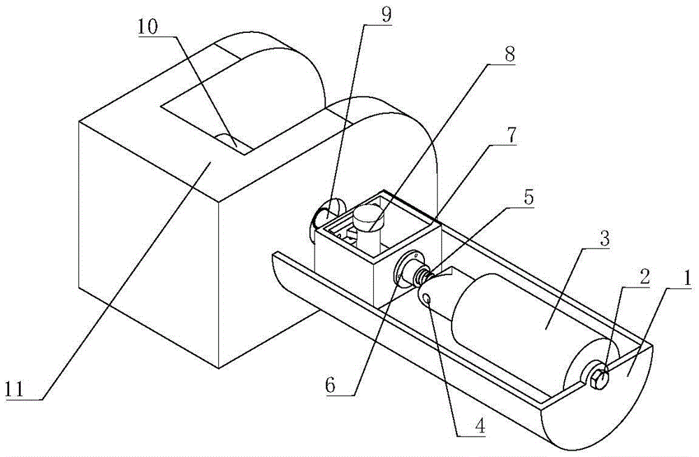
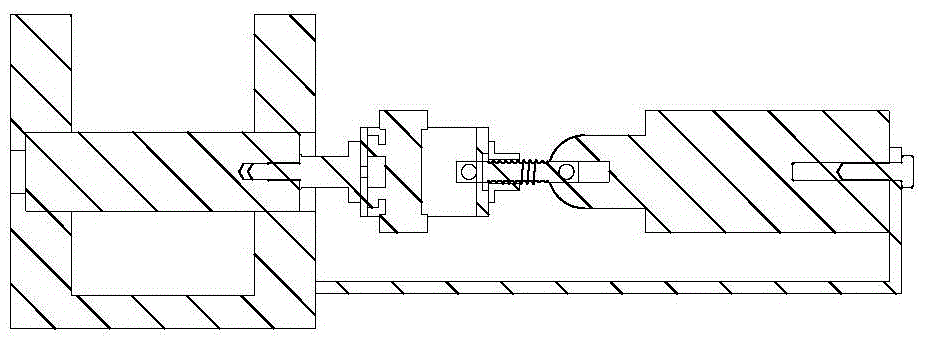
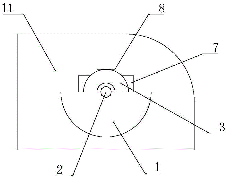
[0032] see figure 1 , a hydraulic support pin removal device provided by the present invention uses compressed air as a power source, includes an axial cylinder 3, a pneumatic vibrator 8, a welding frame 7, and a ball screw 5, and uses a semi-cylindrical sleeve 1 as a The fulcrum is pulled axially, and the axial movement, overall vibration and local rotation can be realized simultaneously during the disassembly process of the pin shaft. The pneumatic vibrator 8 is installed on the welding frame 7, the welding frame 7 is welded with the stepped pin 9, the stepped pin 9 is installed at the end of the pin shaft 10, the ball screw 5 is connected with the welding frame 7 through the screw nut 6, During the disassembly process of the pin shaft 10, the axial cylinder 3 provides the axial pulling force and at the same time plays the role of automatically rotating the pin shaft 10. The semi-cylindrical sleeve 1 is fixed to the outer wall of the axial cylinder 3 by the set screw 2, and ...


PUM


Abstract

The invention discloses a hydraulic support hinge pin detaching device. The hydraulic support hinge pin detaching device comprises an axial cylinder, a pneumatic vibrator, a welding rack and a ball screw, wherein a semi-cylindrical sleeve serves as an axial pulling fulcrum, and axial movement, integral vibration and local rotation can be realized simultaneously. The pneumatic vibrator is mounted on the welding rack, the welding rack is welded with a stepped dowel, the stepped dowel is mounted at an end of the hinge pin, the ball screw is connected with the welding rack through a lead screw nut, the effect of rotating the hinge pin automatically is achieved while axial tension is provided through the axial cylinder, the semi-cylindrical sleeve is fixed with the outer wall of the cylinder, the other end of the semi-cylindrical sleeve is propped against the surface of the hydraulic support during operation, and the axial pulling fulcrum is provided. Compressed air serves as a power source, the hinge pin detaching efficiency can be improved obviously, one-step detaching success rate can be improved by pulling, reversing and vibrating combination operation, destructive detachment is avoided effectively, and the problem that an existing hydraulic support hinge pin is difficult to detach and the like is solved.

Description

technical field [0001] The invention belongs to the technical field of mining machinery, and in particular relates to a hydraulic support pin dismounting device. Background technique [0002] The hydraulic support is a structure used to control the mine pressure in the coal mining face. The demand for large hydraulic supports in the market is increasing day by day. The large hydraulic supports are large in size and heavy in weight. During the manufacturing process, the large hydraulic supports need to be disassembled into components. , to facilitate repair, transportation, and downhole, but the disassembly of the hydraulic support pin is also a very difficult problem. The reasons for the difficulty of disassembly are as follows: [0003] 1. If the support is not used for a long time underground, the main structural parts of the hydraulic support will be hinged, the pin shaft will be seriously corroded, and small particles such as sand and dust in the well will easily enter t...

Claims


Application Information

Patent Timeline
Patent Type & Authority Applications(China)
IPC IPC(8): B25B27/02
CPCB25B27/026
Inventor 阮学云郭永存吴吉莹马强强苏童刘丹丹丁恒
Owner YANCHENG SHENGHUA COAL MASCH CO LTD
Why Eureka
Try Eureka