clutch removal device

A technology for disassembling devices and clutches, which is applied in metal processing, metal processing equipment, manufacturing tools, etc., and can solve problems such as potential safety hazards for operators, damage or even scrapping of the first working tooth 212, time-consuming and laborious problems, and avoid potential safety hazards. The effect of high work efficiency

Active Publication Date: 2017-02-22
KUSN INFOVISION OPTOELECTRONICS
View PDF5 Cites 0 Cited by
  • Summary
  • Abstract
  • Description
  • Claims
  • Application Information

AI Technical Summary

Problems solved by technology

This kind of percussion-type way of enlarging the gap between the first working tooth 212 and the second working tooth 222 is easy to cause the clutch 220 to break due to the limitation of tools such as flat lifters or crowbars and the force direction of the tools and the working space. The second working tooth 222 and the first working tooth 212 of the driving device 210 are damaged or even scrapped, resulting in increased production costs
In addition, this knocking method of enlarging the gap between the first working tooth 212 and the second working tooth 222 will not only bring potential safety hazards to the operator, but also be time-consuming and laborious, and the removal efficiency is low

Method used


Image

  • clutch removal device
  • clutch removal device
  • clutch removal device

Examples


Embodiment Construction

[0024] In order to further explain the technical means and effects of the present invention to achieve the intended purpose of the invention, the specific implementation, structure, characteristics and effects of the clutch removal device proposed according to the present invention will be described below in conjunction with the accompanying drawings and preferred embodiments. The details are as follows:

[0025] The aforementioned and other technical contents, features and effects of the present invention will be clearly presented in the following detailed description of preferred embodiments with reference to the drawings. Through the description of specific implementation methods, the technical means and effects of the present invention to achieve the intended purpose can be understood more deeply and specifically, but the attached drawings are only for reference and description, and are not used to explain the present invention limit.

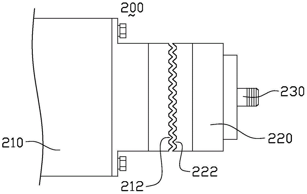
[0026] figure 2 It is a structura...


PUM


Abstract

A clutch dismounting device comprises an annular support and a plurality of ejector rod assemblies. The annular support comprises a first inner surface and a first outer surface, and is provided with a plurality of mounting holes penetrating through the first inner surface and the first outer surface, and the ejector rod assemblies are fixed in the mounting holes respectively. The ejector rod assemblies comprise ejector rods and driving portions, the ejector rods penetrate through the first inner surface, the length direction of the ejector rods is arranged in the radial direction of the annular support, and the driving portions penetrate through the first outer surface and drive the ejector rods to move close to or away from the circle center of the annular support. The clutch dismounting device is simple in structure, convenient to operate, high in dismounting efficiency and capable of effectively preventing a clutch gear from being damaged in the dismounting process.

Description

technical field [0001] The invention relates to the field of roller coating machinery, in particular to a clutch dismounting device for assisting the disassembly of the clutch of a roller coating machine. Background technique [0002] figure 1 It is a schematic diagram of the partial structure of the clutch mechanism used in the roller coater. Such as figure 1 As shown, the clutch mechanism 200 used in the roller coating machine mainly includes a driving device 210 , a clutch 220 and a roller connecting shaft 230 . The drive device 210 has a first working tooth 212 . The clutch 220 includes a second working tooth 222 engaged with the first working tooth 212 of the driving device 210 . The roller connecting shaft 230 is connected to an end of the clutch 220 where the second working tooth 222 is not provided. Through the engagement of the first working teeth 212 and the second working teeth 222 , the driving device 210 drives the clutch 220 to rotate, and then drives the ...

Claims


Application Information

Patent Timeline
Patent Type & Authority Patents(China)
IPC IPC(8): B23P19/02
CPCB23P19/025
Inventor 苗健
Owner KUSN INFOVISION OPTOELECTRONICS
Why Eureka
Try Eureka