Gearbox with shift mechanism

A technology of shifting mechanism and gearbox, applied in belt/chain/gear, components with teeth, mechanical equipment, etc., can solve the problems of gearbox impact, damage to gearbox, inability to adjust gear pair meshing backlash, etc.

Active Publication Date: 2017-10-10
CHANGZHOU RUITAI ENG MASCH CO LTD +1
View PDF5 Cites 0 Cited by
  • Summary
  • Abstract
  • Description
  • Claims
  • Application Information

AI Technical Summary

Problems solved by technology

[0003] There are mainly two types of existing track-type shifting mechanisms: one is the 08-32 type tamping vehicle auxiliary drive axle gearbox introduced from Plasser﹠Theurer Company, which shifts gears by shifting gears, and uses cylinders to Push the shift fork, and the shift fork drives the gear to slide on the spline shaft to realize the gear shift. The shift mechanism can only change the meshing state of the gear pair, but cannot change the meshing center distance of the gear pair, so the meshing side of the gear pair cannot be adjusted. The other is the shift drive cylinder mentioned in the patent 201210516004.6-gearbox to push the horizontal push block to drive the connecting plate to link the turret to swing, so as to realize the engagement and disengagement of the intermediate gear shaft and the output gear, wherein the two ends of the connecting plate The center distance of the hinged hole is fixed, the position of the shift mechanism after the gear is engaged and disengaged is uniquely determined, and the meshing center distance and meshing backlash of the gear pair are also uniquely determined accordingly. If the gear meshing backlash is too large, the vehicle will frequently change direction, which will cause frequent impacts on the gearbox and seriously damage the gearbox. If the gear meshing backlash is too small, the gearbox may be damaged during operation due to The increase of internal temperature leads to further reduction of the meshing backlash of the gear pair, resulting in the gear pair being stuck and seriously damaging the gearbox. The above-mentioned patent 201210516004.6-In order to change the meshing backlash of the gear pair in the gearbox, it is necessary to change the hinge at both ends of the connecting plate The center distance of the hole, because before the product is assembled, there are many factors that affect the meshing backlash of the final gear pair, such as the machining accuracy and dimensional error of the box, the bearing hole of the turret and each connecting piece, the installation clearance of the bearing and the clearance of the gear. Tooth surface accuracy, etc. These factors lead to the inability to accurately judge the meshing backlash interval of the final gear pair before assembly, so in order to achieve the final meshing backlash to meet the design requirements, it is adjusted by changing the center distance of the hinged holes at both ends of the connecting plate. It is necessary to prepare a large number of connecting plates with different center distances in different gradients. During debugging, it is necessary to continuously debug to the required meshing side clearance. This design method consumes a lot of materials, costs and labor time costs. At this time, due to the wear of the gear pair transmission, the actual meshing backlash must be enlarged compared with the factory. At this time, a large number of matching connecting plates are required to meet the reasonable meshing backlash requirements.

Method used


Image

  • Gearbox with shift mechanism
  • Gearbox with shift mechanism
  • Gearbox with shift mechanism

Examples


Embodiment Construction

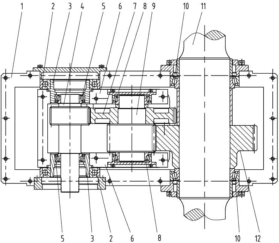
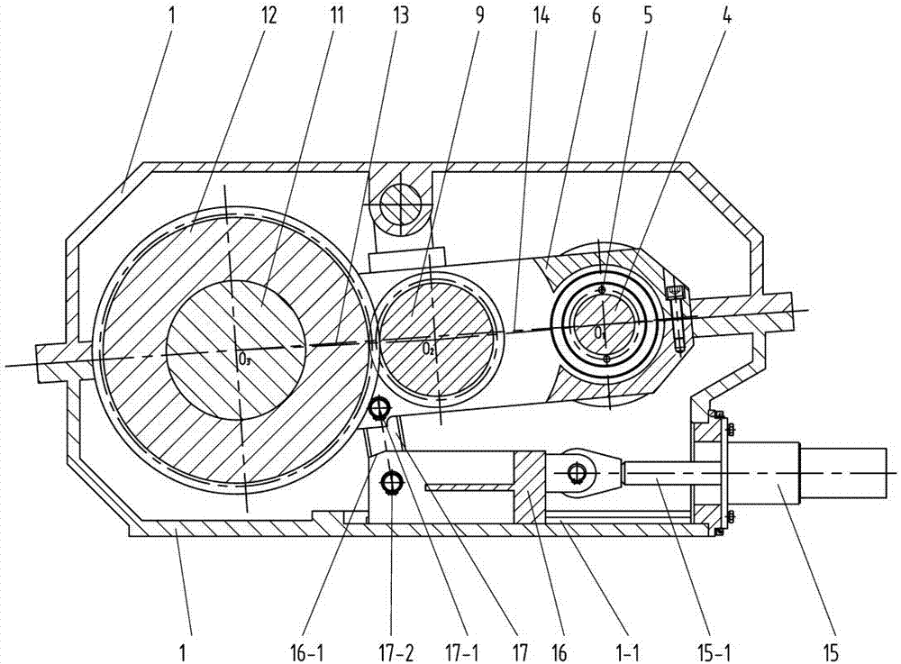
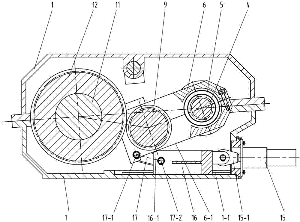
[0019] Such as figure 1 , 2 , 3, 4, and 5, a gearbox with a shift mechanism of the present invention includes a box body 1, an input bearing seat 3, a turret 6, a first rolling bearing 2, a second rolling bearing 5, and a third rolling bearing 8. , The fourth rolling bearing 10, the input gear shaft 4, the intermediate gear shaft 9, the intermediate gear 7, the output gear 12, the output shaft 11, the connecting plate 17, the horizontal push block 16 and the shift power source 15, the input gear shaft 4 and The intermediate gear 7 is constantly meshed. One end of the turret 6 is fixedly connected to the input bearing housing 3. The input bearing housing 3 is supported on the housing 1 through the first rolling bearing 2, and the input gear shaft 4 is supported on the input through the second rolling bearing 5. On the bearing seat 3, the intermediate gear 7 is fixedly connected to the intermediate gear shaft 9, the intermediate gear shaft 9 is supported on the other end of the tu...


PUM


Abstract

The invention discloses a gearbox with a shift mechanism. The gearbox comprises a box body, an input bearing block, a rotary frame, a first rolling bearing, a second rolling bearing, a third rolling bearing, a fourth rolling bearing, an input gear shaft, an intermediate gear shaft, an intermediate gear, an output gear, an output shaft, a connecting plate, a horizontal push block and a gear shifting power source; the connecting plate comprises a first plate, a second plate and an adjusting shim; the first plate is provided with a cylindrical rod, while the second plate is provided with a cylindrical hole, and the cylindrical rod is in movable fit with the cylindrical hole; the adjusting shim is disposed between the first plate and the second plate; an engagement center line O1O2 of the input gear shaft and the intermediate gear intersects with an engagement center line O2O3 of the intermediate gear shaft and the output gear at an angle of 175-179 degrees; further, an inclined edge is formed on an upper portion of the front end of the horizontal push block and capable of contacting with a bottom edge of the rotary frame. The gearbox with the shift mechanism is stable in gear shifting process, simple and convenient to operate, and reasonable in structure; and an engagement center distance of the gear pair can be changed, such that an engagement backlash of the gear pair can be adjusted.

Description

Technical field [0001] The invention relates to a gear box, in particular to a rail-type shift gear box. Background technique [0002] Track-type shift gearbox, through the shift mechanism to realize the conversion between different gears of the whole vehicle, adapt to the requirements of different operating conditions of the whole vehicle. [0003] The existing track-type shifting mechanism mainly has two forms: one is the 08-32 type tamping vehicle auxiliary drive axle gearbox imported from Plasser﹠Theurer Company, which shifts gears by shifting gears, and it uses cylinders Push the shift fork, and the shift fork drives the gear to slide on the spline shaft to realize the gear shift. The shift mechanism can only change the meshing state of the gear pair, not the center distance of the gear pair, and thus the meshing side of the gear pair cannot be adjusted. The other is the shift drive cylinder mentioned in the patent 201210516004.6-gearbox to push the horizontal push block to d...

Claims


Application Information

Patent Timeline
Patent Type & Authority Patents(China)
IPC IPC(8): F16H59/02F16H61/30
CPCF16H59/02F16H61/30
Inventor 张志强朱朝江邱彦杰陈亚东
Owner CHANGZHOU RUITAI ENG MASCH CO LTD
Why Eureka
Try Eureka