Clamp for clamping electronic component

A technology of electronic components and fixtures, which is applied in the field of clamps for clamping electronic components, and can solve the problems of insufficient clamping force, small size tolerance of power transistors, and limited clamping area, etc.

Inactive Publication Date: 2016-04-06
DELTA ELECTRONICS INC
View PDF5 Cites 3 Cited by
  • Summary
  • Abstract
  • Description
  • Claims
  • Application Information

AI Technical Summary

Problems solved by technology

Transistor clips are mostly made of bent metal sheets, and each pin of the power transistor is connected to a high current when it is in operation, so if the clamping point of the transistor clip is too close to the pins of the power transistor, it is easy to cause a short circuit
[0005] Based on the above limitations, the existing transistor must be clamped away from the pins, and it cannot clamp the lower height on the surface of the crystal.
The available clamping area of ​​existing transistor clips is quite limited, so it cannot provide sufficient clamping force, and it is easy to fall off due to holding or long-term use of elastic fatigue
[0006] Furthermore, the dimensional tolerance at the thinner part of the power transistor is smaller, and it can withstand greater pressure. Compared with the thicker part, it is a better clamping point, but the existing transistor clamps cannot be clamped due to the above limitations. Hold at the best gripping point

Method used


Image

  • Clamp for clamping electronic component
  • Clamp for clamping electronic component
  • Clamp for clamping electronic component

Examples


Embodiment Construction

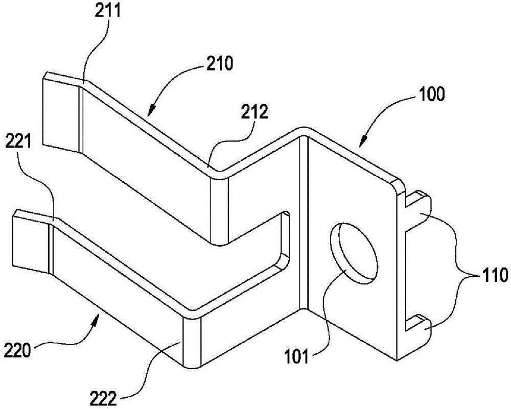
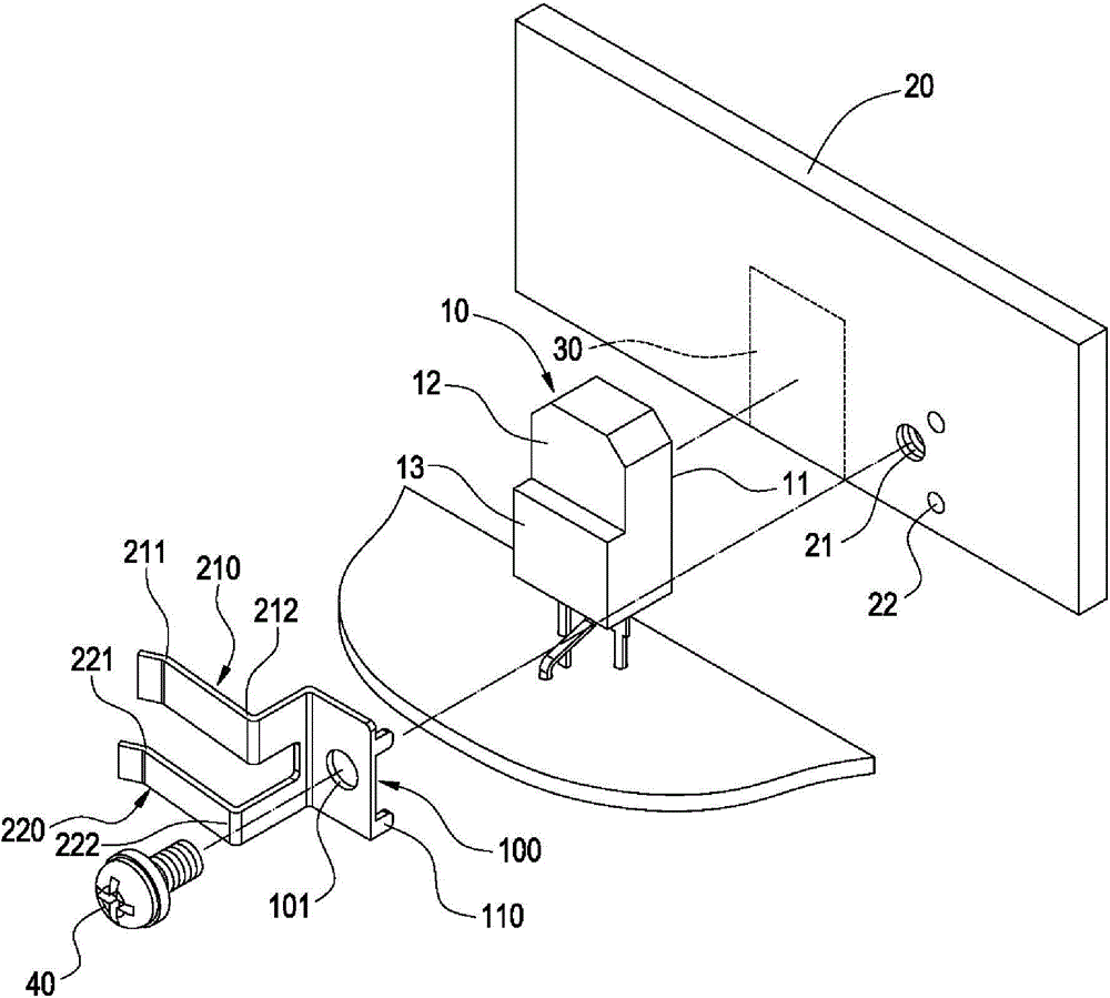
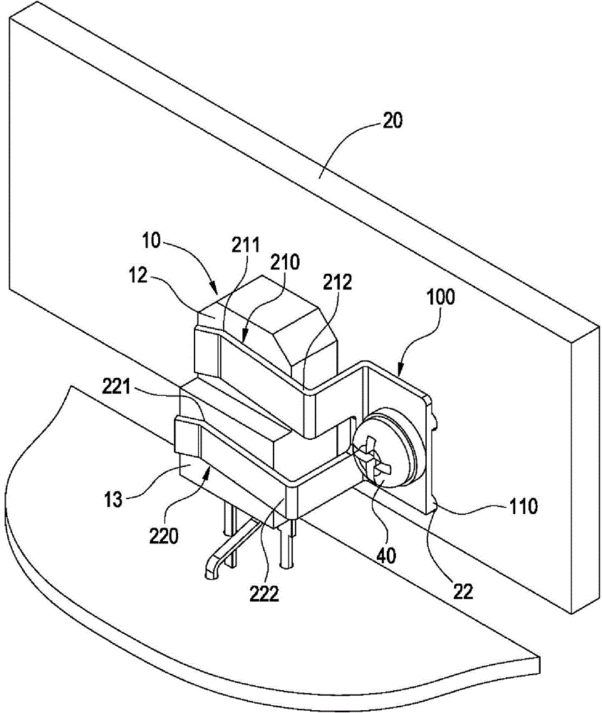
[0038] See Figure 1 to Figure 3 The first embodiment of the present invention provides a clamp for clamping electronic components, which is used to clamp and attach an electronic component 10 to a heat sink 20, which includes a body 100 and a plurality of clamping jaws 210 / 220 .

[0039] In this embodiment, the main body 100 is preferably a rectangular sheet metal body, the main body 100 is provided with a through hole 101, and a plurality of positioning pins 110 are preferably extended from an edge of the main body 100, and each positioning pin 110 is bent. Vertical body 100.

[0040] In this embodiment, the other edge of the main body 100 extends two clamping jaws 210 / 220 arranged opposite to the positioning pins 110, but the present invention does not limit the number of clamping jaws 210 / 220. Each clamping jaw 210 / 220 is a bent long metal sheet, and the two clamping jaws 210 / 220 are arranged parallel to each other. The ends of each clamping jaw 210 / 220 are bent to form a cl...


PUM


Abstract

The invention discloses a clamp for clamping an electronic component. The clamp comprises a body and a plurality of claws, wherein the claws extends out from the edge of the body, and each claw forms a clamping part for pressing against the electronic component, and the clamping parts are arranged on at least two different planes. By adopting the different claws, the clamp can apply the optimal clamping forces on different clamping positions.

Description

Technical field [0001] The present invention relates to a clamp for clamping electronic components, in particular to a clamp with multiple clamping jaws. Background technique [0002] The power transistor is a type of transistor. The general power transistor will generate high temperature when operating at high current. Therefore, it is necessary to attach the power transistor to a heat sink to remove the heat generated by the power transistor. In order to effectively conduct heat from the power transistor to the heat sink, the heat sink and the power transistor must be clamped so that the contact surfaces of the two are closely attached, thereby reducing the gap between the two and obtaining a good Thermal conductivity. [0003] The common clamping mechanism nowadays is a transistor clamp. There are generally two types of transistor clamps, one of which is to lock the heat sink and extend a clamping claw to press the power transistor on the heat sink; the other type It is a U-sh...

Claims


Application Information

Patent Timeline
Patent Type & Authority Applications(China)
IPC IPC(8): H01L21/687
Inventor 刘希安谢宏昌颜仕铭
Owner DELTA ELECTRONICS INC
Why Eureka
Try Eureka