
A traffic channel allocation method and base station

A technology of traffic channel and allocation method, applied in the field of traffic channel allocation method and base station, can solve the problems of wasting channel resources, wasting channel resources, exhausting traffic channels, etc., to avoid blind allocation and improve channel utilization.

Active Publication Date: 2019-01-15
HARBIN HYTERA TECH CORP
View PDF10 Cites 0 Cited by
  • Summary
  • Abstract
  • Description
  • Claims
  • Application Information

AI Technical Summary

Problems solved by technology

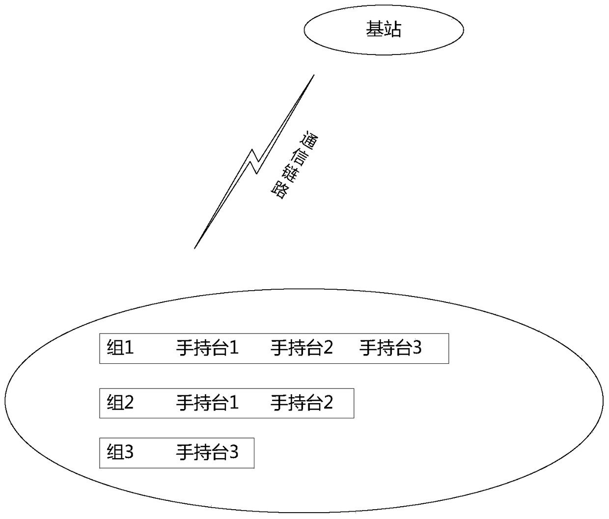
[0006] In this method, the base station allocates a traffic channel for a group call to the terminals belonging to the same group within its jurisdiction, but in practical applications, a terminal may belong to multiple different groups, so when a terminal belongs to multiple When a group initiates a group call within the same time period, the base station needs to allocate a service channel for each group call, and also allocate multiple service channels for a terminal, but a terminal can only participate in one call within a time period, which is impossible Attached to multiple service channels at the same time, therefore, the multiple service channels allocated to the terminal are a serious waste of channel resources. When the group call service is frequent, the service channels of the base station will be quickly exhausted, resulting in serious call loss.
[0007] Compared with the first static allocation method of traffic channels, the dynamic allocation method of traffic channels has certain advantages in the case of infrequent group calls, but in the case of frequent group calls, the second dynamic allocation method of traffic channels will also Serious waste of channel resources
[0008] Both of the above two methods have the problem of wasting channel resources to varying degrees. In today’s shortage of channel resources, people pay more attention to how to effectively allocate service channels for group call services, so as to achieve real on-demand allocation of service channels and rational use of service channels. purpose of channel

Method used


Image

  • A traffic channel allocation method and base station
  • A traffic channel allocation method and base station
  • A traffic channel allocation method and base station

Examples


Embodiment Construction

[0051] The technical solutions in the embodiments of the present invention will be clearly and completely described below in conjunction with the accompanying drawings in the embodiments of the present invention. Obviously, the described embodiments are only some of the embodiments of the present application, not all of them. Based on the embodiments in this application, all other embodiments obtained by persons of ordinary skill in the art without making creative efforts belong to the scope of protection of this application.

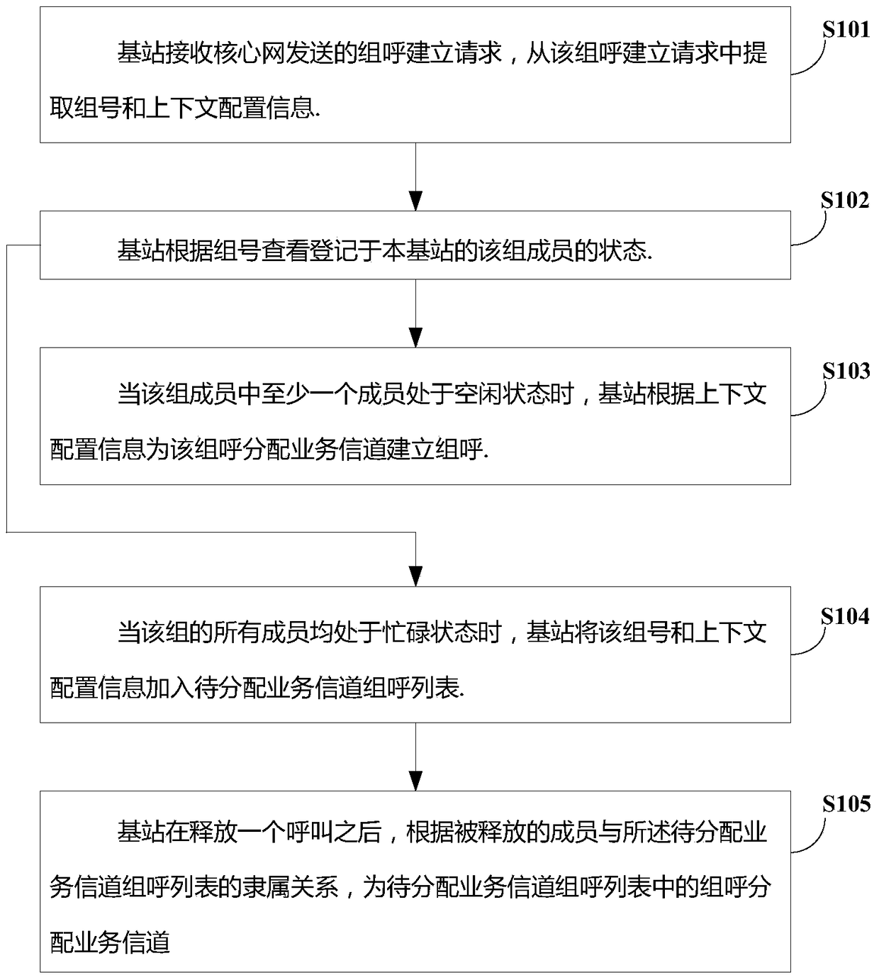
[0052] see figure 1 , figure 1 It is a flowchart of a traffic channel allocation method according to an embodiment of the present invention, and the method includes the following steps:

[0053] S101. The base station receives a group call establishment request sent by a core network, and extracts a group number and context configuration information from the group call establishment request.

[0054] The application scenarios of the embodiments of the p...


PUM


Abstract

The invention discloses a service channel allocation method and device, wherein the method includes: a base station receives a group call establishment request sent by a core network, and extracts a group number and context configuration information from the group call establishment request; the base station checks and registers according to the group number The status of the group members of the base station; when at least one member of the group is in the idle state, the base station allocates a traffic channel for the group call to establish a group call according to the context configuration information; when all members of the group are in the busy state , the base station adds the group number and context configuration information to the group call list of the service channel to be allocated; The traffic channel assigned to the group call in the traffic channel group call list. Utilizing the present invention can achieve on-demand distribution of service channels and improve channel utilization.

Description

technical field [0001] The present invention relates to the technical field of communications, and more specifically, to a service channel allocation method and a base station. Background technique [0002] At present, there are mainly two methods for allocating service channels for group calls in the trunking system, and the two methods are as follows: [0003] 1. Static allocation method of traffic channels [0004] The method is based on a preset group call area, and the base station in the group call area allocates a traffic channel for the group call service. No matter whether there is a registered member of the group call within the jurisdiction of the base station, the base station must allocate a service channel for the group call. Traffic channel, this method wastes channel resources. [0005] 2. Dynamic channel allocation method [0006] In this method, the base station allocates a traffic channel for a group call to the terminals belonging to the same group wit...

Claims


Application Information

Patent Timeline
Patent Type & Authority Patents(China)
IPC IPC(8): H04W72/00
CPCH04W72/30H04W72/00
Inventor 谭建安邓万发
Owner HARBIN HYTERA TECH CORP
Learn More