Paperboard gluing machine with automatic clamping and conveying mechanism

A technology of clamping, conveying and moving mechanisms, which is applied to devices and coatings that apply liquid to the surface. Gluing effect, good effect, uniform gluing effect

Active Publication Date: 2016-04-13
江苏捷飞环保科技有限公司
View PDF7 Cites 12 Cited by
  • Summary
  • Abstract
  • Description
  • Claims
  • Application Information

AI Technical Summary

Problems solved by technology

[0002] The cardboard used in existing corrugated boxes generally needs to be formed by multi-layer pasting, and the pasting needs to be glued. The existing gluing device is generally equipped with two upper and lower transmission rollers, and the cardboard is squeezed from between the two transmission rollers. When the glue is applied to the cardboard, the existing glue tank is fixed, and the driving roller can be adjusted up and down according to the needs. When the distance between the upper driving roller and the glue tank is too large, it will affect the glue dripping. Uniformity and effect on the drive roller, thus affecting the subsequent gluing
[0003] Moreover, the existing feeding is generally manual feeding, which needs to manually push the end of the cardboard to be clamped between the two transmission rollers, and also needs people to hold the cardboard at all times to prevent it from shifting, which is inefficient and easy to operate. people get glue

Method used


Image

  • Paperboard gluing machine with automatic clamping and conveying mechanism
  • Paperboard gluing machine with automatic clamping and conveying mechanism
  • Paperboard gluing machine with automatic clamping and conveying mechanism

Examples


Embodiment

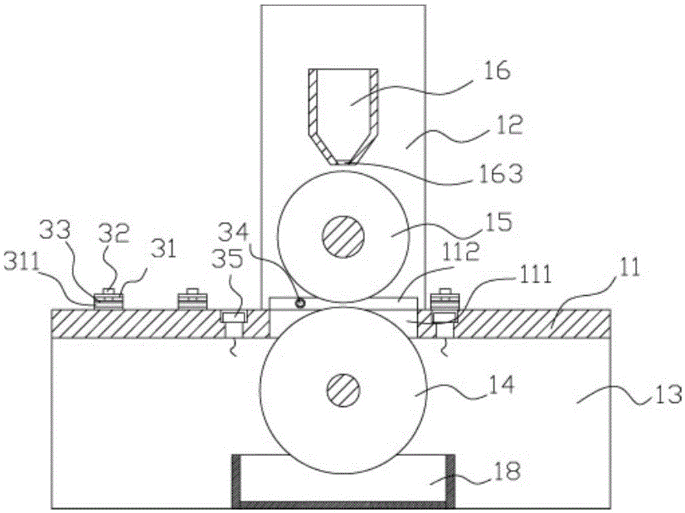
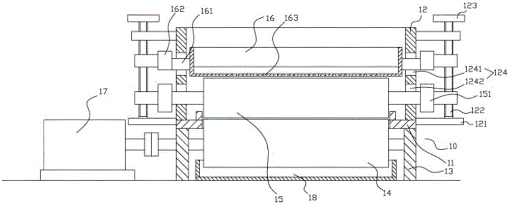
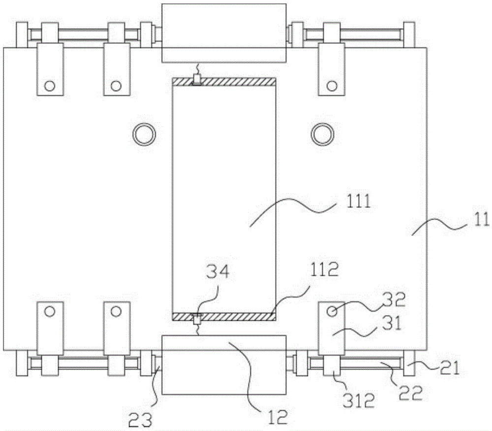
[0023] Example: see Figure 1 to Figure 4 As shown, a gluer on cardboard with an automatic clamping and conveying mechanism includes a frame 10, two vertical plates 12 are fixed on the top surfaces of both sides of the platen 11 of the frame 10, and the two vertical plates 12 of the platen 11 are There are support plates 13 fixed on the side bottom surface, and the two ends of the lower transmission pressure roller 14 are hinged on the two support plates 13, and the lower transmission pressure roller 14 is inserted into the elongated slot 111 provided in the middle of the table 11, the elongated through slot 111 Two limit strips 112 are fixed on the top surface of the platen 11 at the front and rear ends of the groove 111, the top of the lower driving pressure roller 14 stretches out from the top surface of the platen 11, and the two ends of the outer wall of the support plate 13 are A moving mechanism 20 is fixed, and at least two clamping blocks 31 are provided in the moving...


PUM


Abstract

The invention discloses a paperboard gluing machine with an automatic clamping and conveying mechanism. The paperboard gluing machine comprises a rack. Two vertical plates are fixed to the top faces of the two sides of a platen of the rack. Supporting plates are fixed to the bottom faces of the two sides of the platen. The two ends of a lower transmission press roller are hinged to the two supporting plates. The lower transmission press roller is inserted in a long through hole in a sleeved manner, and the long through hole is formed in the middle portion of the platen. Two limiting strips are fixed to the top faces of the parts, at the front end and the rear end of the long through groove, of the platen. Connecting plates are fixed to the upper portions and the lower portions of the outer side walls of the vertical plates. The two ends of adjusting screws are hinged to the two connecting plates. The upper ends of the adjusting screws stretch out of the connecting plate at the upper portion and are fixedly provided with rotary tables. Synchronous ascending and descending of an upper transmission press roller and a gluing groove can be achieved, even gluing is guaranteed, and the gluing effect is improved. Meanwhile, the paperboard gluing machine can automatically clamp a paperboard and convey the paperboard to the part between two transmission rollers to achieve gluing, automatic pulling out and conveying, and the paperboard gluing machine is high in efficiency and good in effect.

Description

Technical field: [0001] The invention relates to the technical field of packaging equipment, in particular to a cardboard gluer with an automatic clamping and conveying mechanism. Background technique: [0002] The cardboard used in existing corrugated boxes generally needs to be formed by multi-layer pasting, and the pasting needs to be glued. The existing gluing device is generally equipped with two upper and lower transmission rollers, and the cardboard is squeezed from between the two transmission rollers. When the glue is applied to the cardboard, the existing glue tank is fixed, and the driving roller can be adjusted up and down according to the needs. When the distance between the upper driving roller and the glue tank is too large, it will affect the glue dripping. The uniformity and effect on the drive roller, thus affecting the subsequent gluing. [0003] Moreover, the existing feeding is generally manual feeding, which needs to manually push the end of the cardbo...

Claims


Application Information

Patent Timeline
Patent Type & Authority Applications(China)
IPC IPC(8): B05C1/12B05C13/02B05C11/11
CPCB05C1/0813B05C1/0821B05C1/083B05C1/12B05C11/10B05C11/11B05C13/02
Inventor 吕晶晶
Owner 江苏捷飞环保科技有限公司
Why Eureka
Try Eureka