Screw feeding device

A supply device and screw technology, which is applied in the direction of transportation and packaging, conveyor objects, etc., can solve the problems of screw flipping and material jamming, and achieve the effect of improving feeding efficiency and automation

Inactive Publication Date: 2016-04-13
IND TECH RES INST
View PDF5 Cites 10 Cited by
  • Summary
  • Abstract
  • Description
  • Claims
  • Application Information

AI Technical Summary

Problems solved by technology

However, the air-blowing automatic locking screw machine itself is limited by the shape of the screw and the aspect ratio (the ratio of the length of the thread to the diameter of the head), not every kind of screw is suitable for the air-blowing automatic locking screw machine, especially When the length of the thread of the screw is too short, the screw is prone to flipping or jamming during the process of conveying the screw to the screwdriver head in the pipeline of the air-blowing automatic screw locking machine

Method used


Image

  • Screw feeding device
  • Screw feeding device
  • Screw feeding device

Examples


Embodiment Construction

[0081] The implementation of the present invention is described below through specific specific implementation forms. Those skilled in the art can easily understand other advantages and effects of the present invention from the content disclosed in this specification, and can also be implemented or applied through other different specific implementation forms.

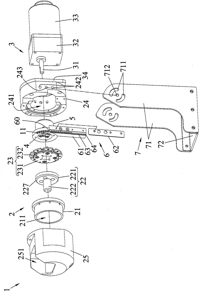
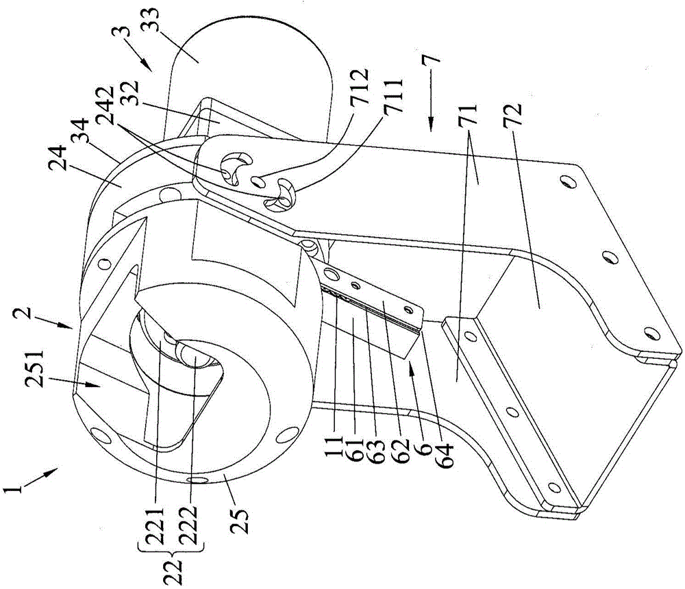
[0082] Figure 1A To illustrate an exploded perspective view of the screw supply device 1 of the present invention, Figure 1B to Figure 1D It is a perspective view showing different combinations of the screw supply device 1 in FIG. 1 of the present invention, wherein, Figure 1D One of the two supporting elements 71 is not shown, Figure 1E The supply housing 25 is not shown.

[0083] Such as Figure 1A to Figure 1E As shown, the screw supply device 1 mainly includes a supply module 2 and a power module 3 .

[0084] The feeding module 2 has a hollow shell 21, a material shifting element 22 and a sieve turntable 23,...


PUM


Abstract

The invention provides a screw feeding device. The screw feeding device includes a feeding module and a power module. The feeding module has a material sieving rotary table and a hollow shell arranged on the material sieving rotary table, an accommodating space is formed between the surface of the material sieving rotary table and the hollow shell to accommodate a plurality of screws, and a plurality of accommodating units corresponding to the shapes of the screws are formed between the periphery of the material sieving rotary table and the hollow shell, so as to accommodate and array the screws from the accommodating space through the accommodating units. The power module is connected with the feeding module, and provides power o rotate the hollow shell and the material sieving rotary table, thereby transmitting the screws arrayed by the accommodating unit to predetermined positions. Thus, the screw feeding device can rapidly array and transmit the screws in the accommodating space, so as to improve feeding efficiency.

Description

technical field [0001] The present invention relates to a screw supply device, in particular to a rotary screw supply device. Background technique [0002] In today's many manufacturing industries of 3C products, electronics, motors, machinery, hardware, toys and furniture, the assembly of components, modules and systems is often completed by screw locking. [0003] Generally speaking, in an assembly or workpiece, at least 3 to 4 screws are used, and at most dozens of screws are used for locking. The traditional assembly line often needs to perform screw locking manually, which often consumes a lot of manpower, and the locking quality is not stable. Therefore, an automatic screw locking machine has been developed to replace manual work. [0004] Although the locking action of the automatic screw locking machine is faster than manual locking, and the quality is also better, but after each screw is locked, it is necessary to return to the discharge port of the screw alignment...

Claims


Application Information

Patent Timeline
IPC IPC(8): B65G47/14
Inventor 郭子鑫彭彦嘉
Owner IND TECH RES INST
Why Eureka
Try Eureka