Push device driven by sheave

A technology of pushing device and sheave, which is applied in the direction of lifting device, etc., can solve the problems of intermittent pushing, continuous rotation of connecting rod, difficult control of acceleration, etc., and achieve the effect of stable and reliable movement and avoiding continuous rotation

Inactive Publication Date: 2016-04-13
潘玲玉
View PDF7 Cites 17 Cited by
  • Summary
  • Abstract
  • Description
  • Claims
  • Application Information

AI Technical Summary

Problems solved by technology

The problem with the rod-type push device is that the connecting rod rotates continuously and cannot be pushed intermittently
When multiple rod structures are used to realize intermittent motion, the acceleration of the motion between the rods is difficult to control, and the motion becomes unstable

Method used


Image

  • Push device driven by sheave
  • Push device driven by sheave

Examples


Embodiment Construction

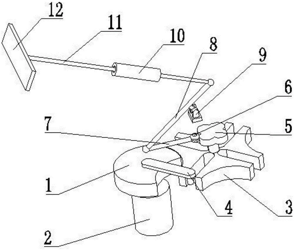
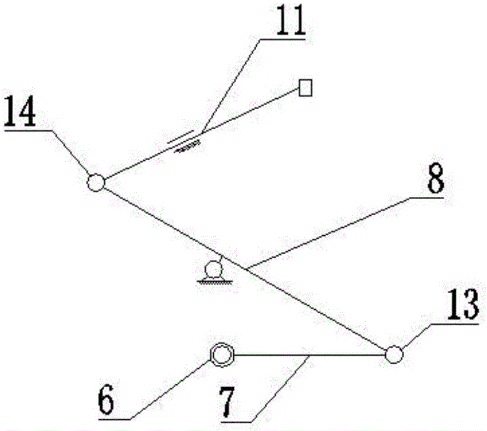
[0016] refer to figure 1 and figure 2 , a sheave driving and pushing device of the present invention includes a driving dial 1, a motor 2, a driven sheave 3, a driving lever 4, a cam 5, a roller 6, a first connecting rod 7, a second connecting rod 8, Bracket 9, sleeve 10, third connecting rod 11 and push plate 12, the bottom of the driving dial 1 is connected to the motor 2 shaft, and the motor 2 is installed on the frame; the driving dial 1 and the driven sheave 3 are composed A sheave mechanism; the driving dial 1 is fixedly connected with a driving lever 4, the driving dial 1 is provided with an inner recess, and the driving lever 4 is located in the inner recess of the driving dial 1; the driven sheave 3 Cam 5 is connected on the geometric central axis of the cam, and the cam 5 and the roller 6 cooperate to move, and the cam 5 and the roller 6 are always in engagement; the first connecting rod 7 is hinged with the second connecting rod 8, and the first connecting rod 7 ...


PUM


Abstract

The invention discloses a push device driven by a sheave. The push device comprises a drive driving plate, a motor, a driven sheave, a drive driving lever, a cam, a roller, a first connecting rod, a second connecting rod, a support, a sleeve, a third connecting rod and a push plate. The bottom of the drive driving plate is connected with a motor shaft, and the motor is arranged on a rack. A sheave mechanism is composed of the drive driving plate and the driven sheave. The drive driving plate is fixedly connected with the drive driving lever, the drive driving plate is provided with an inward concave position, and the drive driving lever is located at the inward concave position of the drive driving plate. The geometrical center axis of the driven sheave is connected with the cam, the cam and the roller move in a matched manner, and the cam and the roller are constantly kept in an engagement state. The first connecting rod and the second connecting rod are hinged, and the second connecting rod and the third connecting rod are hinged. The sheave mechanism and a three-link mechanism are matched, the effect of intermittent pushing is achieved, the requirement for the pushing stroke and the speed can be met, rotation of the connecting rods is avoided, and running is stable and reliable.

Description

【Technical field】 [0001] The invention relates to the technical field of stacker equipment, in particular to the technical field of a sheave-driven pushing device. 【Background technique】 [0002] Stacking equipment is a special crane that uses forks or skewers to grab, carry and stack or access unit goods from high-level shelves. The stacker is the core equipment of the entire automated three-dimensional warehouse. It can move goods from one place to another through manual operation, semi-automatic operation or fully automatic operation. It consists of an upper beam, a lower beam, a column, a horizontal traveling mechanism, a lifting mechanism, a loading platform, a cargo fork and an electrical control system. Stacking equipment is a special lifting machinery developed with the three-dimensional warehouse. The operation requirements are completed by the three driving mechanisms of walking, lifting and fork. The stacker reduces the labor intensity of the warehouse workers a...

Claims


Application Information

Patent Timeline
Patent Type & Authority Applications(China)
IPC IPC(8): B66F9/19B66F9/075
CPCB66F9/195B66F9/07504
Inventor 潘玲玉
Owner 潘玲玉
Why Eureka
Try Eureka