
Longitudinal sleeper vibration damping track and its vibration damping assembly

A technology of vibration damping components and sleepers, which is applied in the direction of tracks, roads, fixed rails, etc., can solve the problems of poor vibration damping effect and achieve good vibration damping effect

Inactive Publication Date: 2018-03-16
BEIJING JSZK RAILWAY TECH
View PDF7 Cites 0 Cited by
  • Summary
  • Abstract
  • Description
  • Claims
  • Application Information

AI Technical Summary

Problems solved by technology

[0005] Although this kind of vibration damping structure has made some progress and has a better vibration damping effect, it still has room for improvement.
In other words, when the speed and load of the train are different, the existing damping structure can not achieve the best vibration damping effect. For example, if the design index makes it have a large The best damping effect, then it usually has a relatively poor damping effect when the train load is small, how to make it have a good damping effect in a wider range is what those skilled in the art want to solve technical problem

Method used


Image

  • Longitudinal sleeper vibration damping track and its vibration damping assembly
  • Longitudinal sleeper vibration damping track and its vibration damping assembly
  • Longitudinal sleeper vibration damping track and its vibration damping assembly

Examples


Embodiment Construction

[0065] In order to better explain the present invention and facilitate understanding, the present invention will be described in detail below through specific embodiments in conjunction with the accompanying drawings.

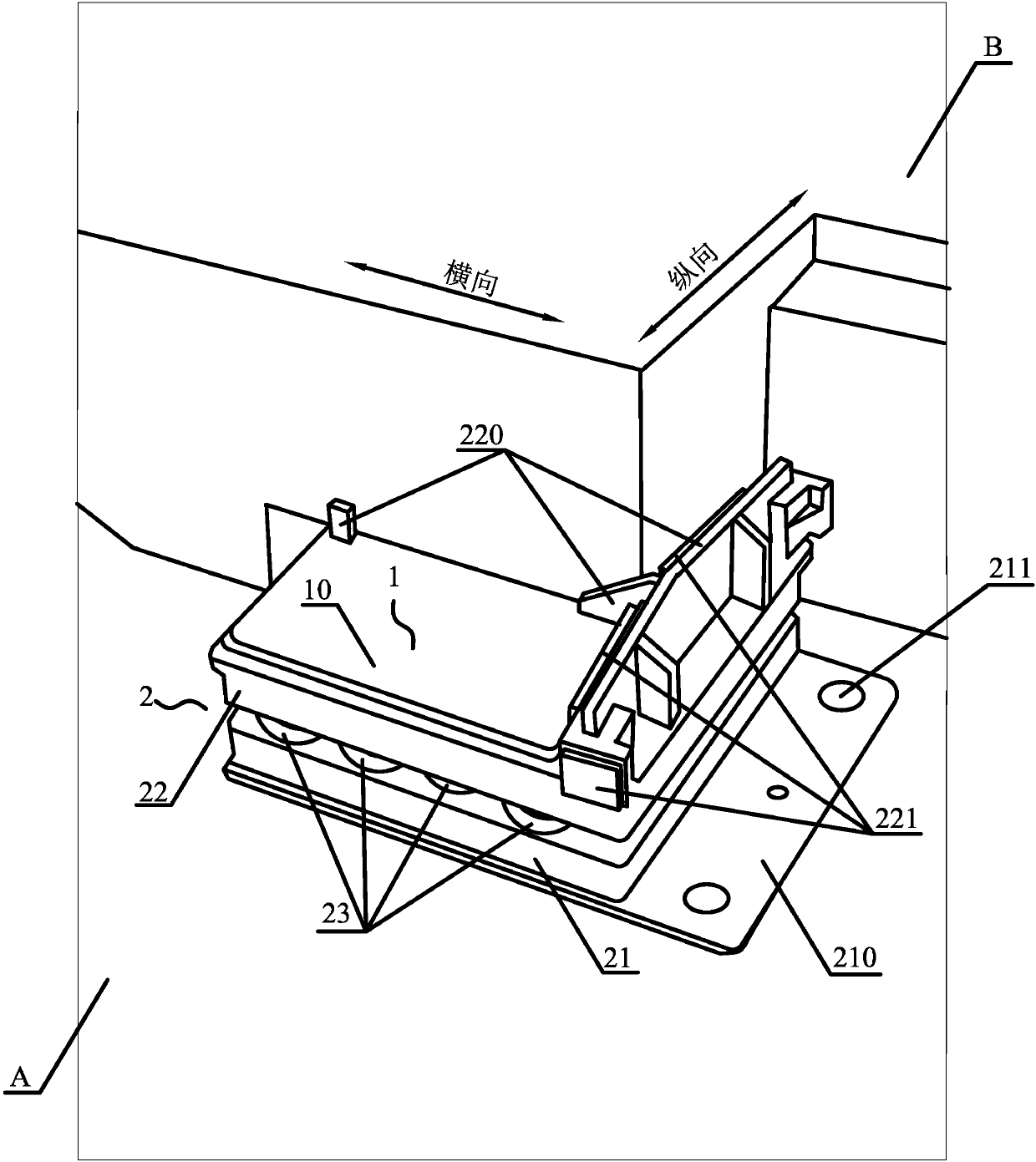
[0066] Referring to Fig. 1 , the vibration damping assembly according to the first embodiment of the present invention has a superimposed first elastic member 1 and a second elastic member 2, and there is a sufficient difference between the elastic forces of the two so that the overall vibration damping assembly is divided into two parts. Stage vibration damping effect (in order to obtain a better vibration damping effect, and at the same time, have higher safety performance and higher durability, preferably the stiffness ratio of the two is between 4.1:5.3 and 3.7:4.4).

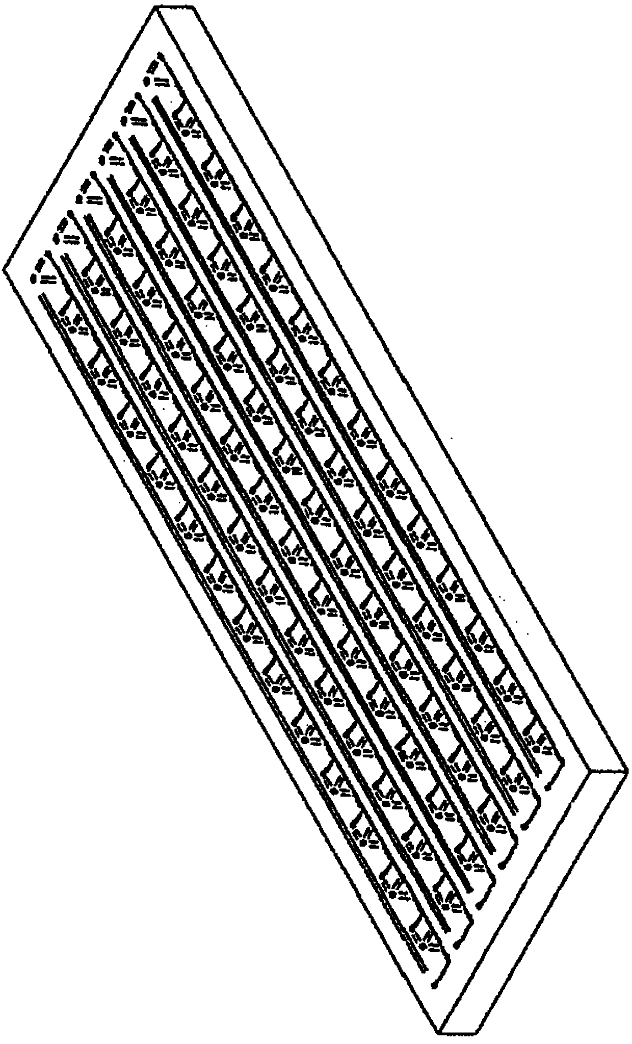
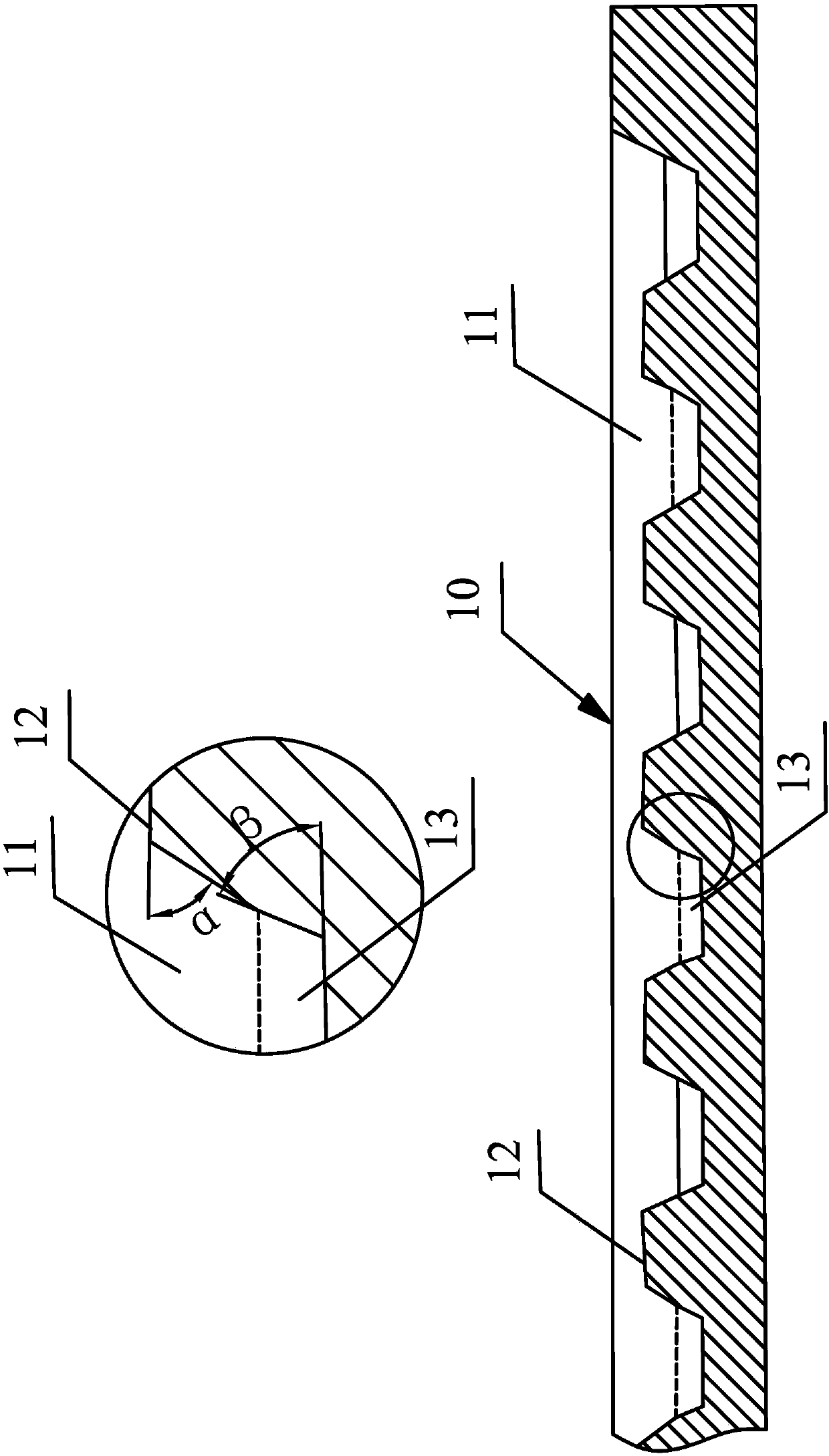
[0067] Wherein, the first elastic member is made of elastic material (such as rubber), and its stiffness can be 18.5±0.3KN / mm 2 ,Such as Figure 1A , Figure 1B As shown, it is plate-shaped ...


PUM


Abstract

A longitudinal sleeper vibration damping rail and a vibration damping component thereof. The longitudinal sleeper vibration damping rail comprises a longitudinal sleeper and the vibration damping component. The vibration damping component elastically supports the longitudinal sleeper. The vibration damping component comprises a superimposed first elastic part (10) and a second elastic part (2), and a sufficient difference exists between an elastic force of the first elastic part (10) and an elastic force of the second elastic part (2) so as to enable the vibration damping component to show a staged vibration damping effect on the whole. The first elastic part (10) is made of an elastic material and is plate-shaped on the whole. A supporting surface of the first elastic part (10) is provided with a plurality of grooves (11) extending transversely. A top surface of a supporting wall (12) between adjacent grooves (11) forms a part of the supporting surface of the first elastic part (10), and a width of an opening of each groove (11) is greater than that of the top surface of the supporting wall (12) between the adjacent grooves (11). The second elastic part (2) comprises a base (21), a top cover (22), and a spring (23) pre-pressed between the base (21) and the top cover (22). An upper surface of the base (21) is provided with a positioning column (212) positioning a lower end of the spring (23), a lower surface of the top cover (22) is provided with the positioning column (212) positioning the upper end of the spring (22), a cross section of each positioning column (212) is triangular on the whole, and a vertex of the triangle is configured to have smooth transition. By means of the rail structure, the effect of vibration damping and noise reduction can be improved.

Description

technical field [0001] The invention relates to a longitudinal sleeper vibration-damping track, which is mainly used for high-speed tracks with high vibration-damping requirements. The invention also relates to a vibration-damping component, which can provide better vibration-damping effects. Background technique [0002] With the development of society and the advancement of technology, there are more and more applications of longitudinal sleepers (or ladder sleepers). Although the longitudinal sleeper has many advantages, its continuous longitudinal beam has the characteristics of high rigidity and weak elasticity, so it has high requirements for vibration and noise reduction. [0003] At present, in response to the vibration and noise reduction requirements of longitudinal sleepers, a certain vibration reduction effect is mainly obtained by installing vibration reduction devices at the positions of ballast beds, sleepers, rails and fasteners. [0004] For example, the Ch...

Claims


Application Information

Patent Timeline
Patent Type & Authority Patents(China)
IPC IPC(8): E01B19/00
CPCE01B19/003E01B2204/06E01B9/68E01B19/00
Inventor 商文明
Owner BEIJING JSZK RAILWAY TECH
Learn More