
An Anisotropic Parameter Inversion Method Based on Transmission Equation

An anisotropic and parametric inversion technology, applied in the field of geophysical inversion, can solve the problems that the accuracy of velocity analysis cannot meet the needs of the method, the influence of anisotropic parameters of transfer errors, and the multiple errors of picking up residual time difference, etc., and reach the range of input data. Controllable, high signal-to-noise ratio and high stability

Active Publication Date: 2018-05-04
CHINA PETROLEUM & CHEM CORP +1
View PDF7 Cites 0 Cited by
  • Summary
  • Abstract
  • Description
  • Claims
  • Application Information

AI Technical Summary

Problems solved by technology

[0002] Anisotropy parameters play a pivotal role in the quantitative prediction of fractures, but because the order of magnitude of anisotropy parameters is much smaller than that of seismic data, it brings great difficulties to its calculation
At present, the calculation of anisotropy parameters is mainly based on prestack azimuth gathers, which are mainly divided into the following three types of channels: 1. According to the velocity information that changes with the seismic azimuth, the accuracy of velocity analysis is difficult to meet the needs of the method; 2. According to the velocity information that varies with the seismic azimuth The remaining time difference information, there are many errors when picking up the remaining time difference; 3. Based on the simplified Ruger (1998) equation (the solution of the unsimplified or approximate Ruger equation cannot be calculated, and the simplified equation or some approximate relationship must be used Simplify Ruger's equation to get the solution of Ruger's equation
And the Ruger equation used in the existing method is the Ruger reflection coefficient equation, not the Ruger transmission equation), based on the inversion of elastic parameters under various assumptions, although the research shows that the simplified Ruger equation has little effect on the calculation of the reflection coefficient, However, the resulting transmission error has a huge influence on the calculation of anisotropy parameters with extremely small orders of magnitude.

Method used


Image

  • An Anisotropic Parameter Inversion Method Based on Transmission Equation
  • An Anisotropic Parameter Inversion Method Based on Transmission Equation
  • An Anisotropic Parameter Inversion Method Based on Transmission Equation

Examples


Embodiment Construction

[0041] Below in conjunction with accompanying drawing, the present invention is described in further detail:

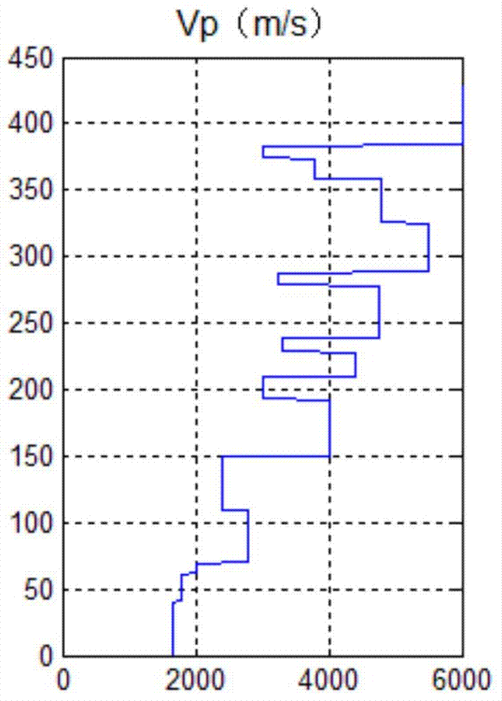
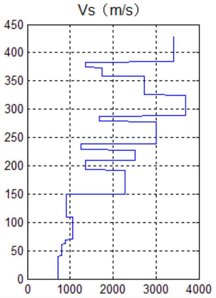
[0042] At present, most anisotropic parameter inversions are based on the simplified Ruger reflection coefficient equation, and the approximation or simplification process introduces errors, while the Ruger transmission equation and the reflection coefficient equation have the same anisotropic characteristics. Therefore, the present invention obtains the anisotropy parameter Δδ based on the complete Ruger transmission coefficient equation (V) , Δε (V) Theoretically, the solution does not introduce errors, and the calculation results are more accurate, and has the advantage of post-stack inversion. The inversion results can be used in hot fields such as fracture prediction and shale gas prediction.

[0043] Based on the complete Ruger transmission equation, the present invention calculates the anisotropy parameter ε (V) ,δ (V) , the method is suitable for HTI (trans...


PUM


Abstract

The invention provides an anisotropic parameter inversion method based on a transmission equation, which belongs to the field of geophysical inversion. The method includes: (1) selecting post-stack seismic data volumes corresponding to any three different azimuth angles, calculating the reflection coefficients corresponding to the three different azimuth angles through sparse pulse inversion method; (2) calculating three different azimuth angles respectively. The transmission coefficient corresponding to the reflection coefficient of the azimuth angle (3) analyze the pre-stack azimuth gather to obtain the incident angle information, the incident angle information includes the maximum incident angle i2, the minimum incident angle i1 and the interval; (4) use the azimuth information transmission coefficient The information is calculated to obtain the anisotropy parameters Δε(V) and Δδ(V).

Description

technical field [0001] The invention belongs to the field of geophysical inversion, and in particular relates to an anisotropic parameter inversion method based on a transmission equation. Background technique [0002] Anisotropy parameters play a pivotal role in the quantitative prediction of fractures, but because the order of magnitude of anisotropy parameters is much smaller than that of seismic data, its calculation has brought great difficulties. At present, the calculation of anisotropy parameters is mainly based on prestack azimuth gathers, which are mainly divided into the following three types of channels: 1. According to the velocity information that changes with the seismic azimuth, the accuracy of velocity analysis is difficult to meet the needs of the method; 2. According to the velocity information that varies with the seismic azimuth The remaining time difference information, there are many errors when picking up the remaining time difference; 3. Based on the...

Claims


Application Information

Patent Timeline
Patent Type & Authority Patents(China)
IPC IPC(8): G01V1/28
Inventor 张克非肖鹏飞李呈呈周单须振华许凯
Owner CHINA PETROLEUM & CHEM CORP
Learn More