
pneumatic tire

A technology for pneumatic tires and tires, which is applied to tire parts, tire tread/tread pattern, transportation and packaging, etc., and can solve the problem that the shoulder land part cannot follow softly, the shoulder land part wears unevenly, and is easy to produce Sliding and other problems, to maintain the handling stability, maintain drainage performance, improve the effect of circumferential rigidity

Active Publication Date: 2018-09-07
SUMITOMO RUBBER IND LTD
View PDF11 Cites 0 Cited by
  • Summary
  • Abstract
  • Description
  • Claims
  • Application Information

AI Technical Summary

Problems solved by technology

[0004] However, in the above-mentioned shoulder land portion, the rigidity at the inner end side of the shoulder lug groove in the tire axial direction is relatively increased, and a large difference in rigidity in the tire axial direction is likely to be formed.
Therefore, the shoulder land portion cannot softly follow the road surface over the entire axial area of ​​the tire, and slippage tends to occur between the shoulder land portion and the road surface.
Such sliding has the problem that uneven wear tends to occur on the shoulder land portion.

Method used


Image

  • pneumatic tire
  • pneumatic tire
  • pneumatic tire

Examples


Embodiment

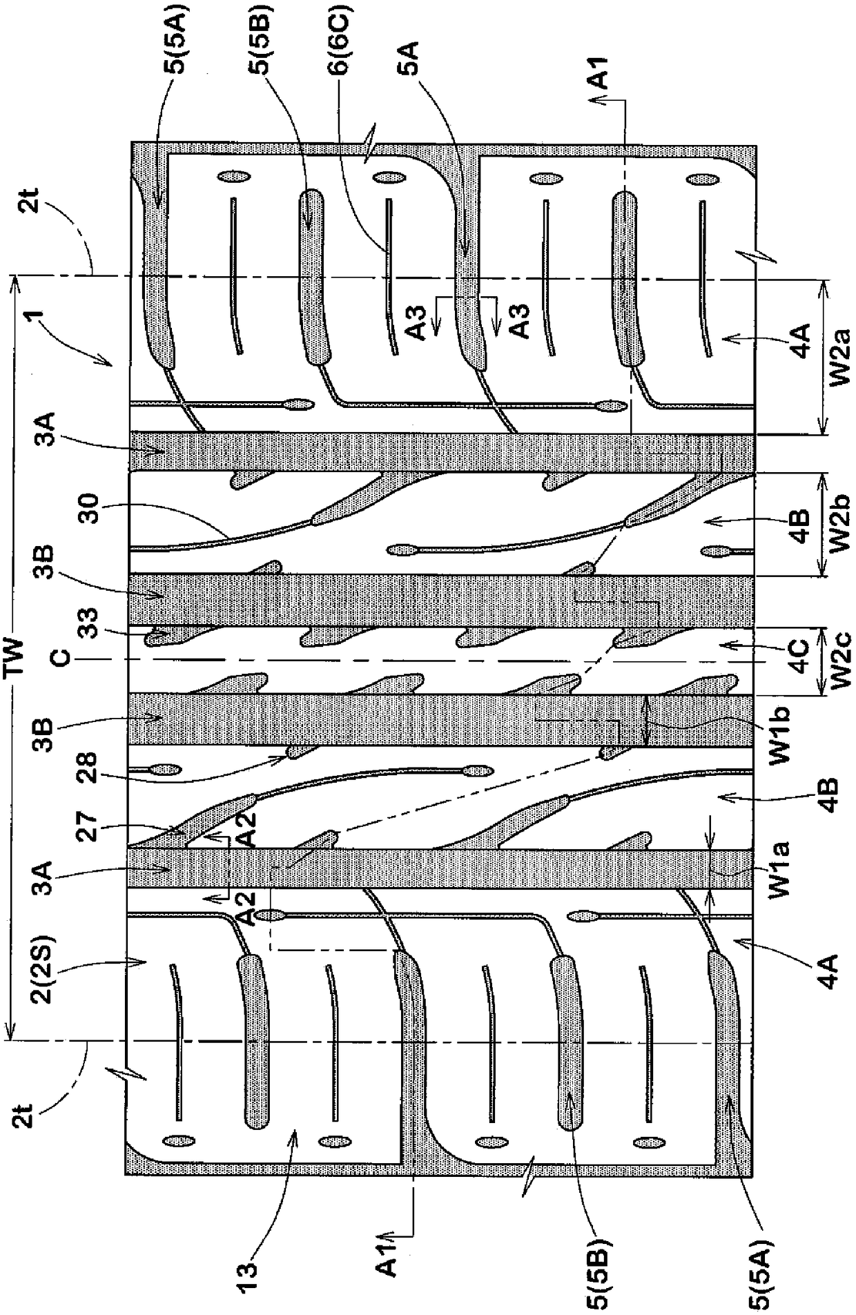
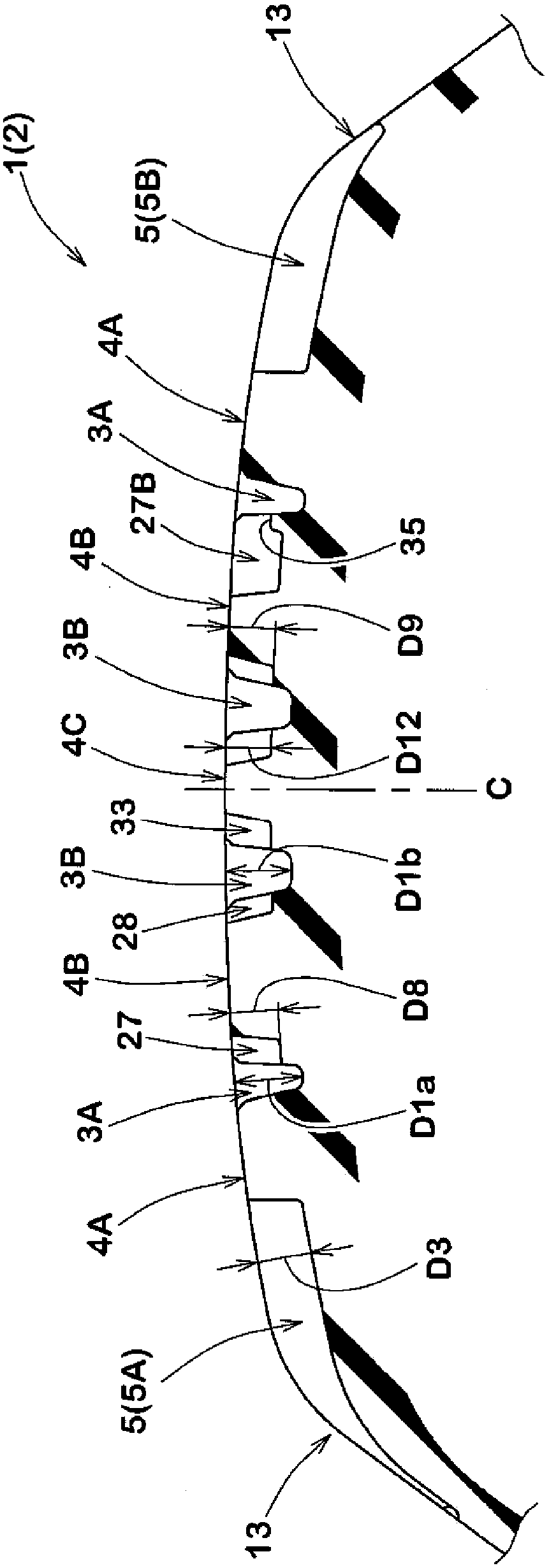
[0095] Made in figure 1 Tires having the basic configuration shown and having the first shoulder sipes, second shoulder sipes and lug grooves shown in Table 1 were evaluated. In addition, for comparison, tires without the first shoulder sipe or the second shoulder sipe (Comparative Example 1, Comparative Example 2, and Comparative Example 3) were also produced and evaluated in the same manner. In addition, the common specifications are as follows.

[0096] Tire size: 195 / 65R15 91H

[0097] Rim size: 15×6.0J

[0098] Internal pressure (the internal pressure specified by the vehicle):

[0099] Front wheel: 230kPa, rear wheel: 220kPa

[0100] Vehicle: Prius manufactured by Toyota Motor Co., Ltd.

[0101] Tread contact width TW: 150mm

[0102] Shoulder main groove:

[0103] Groove width W1a / TW: 10.1%, groove depth D1a: 8.2mm

[0104] Central Main Ditch:

[0105] Groove width W1b / TW: 13.5%, groove depth D1b: 8.2mm

[0106] Chamfer:

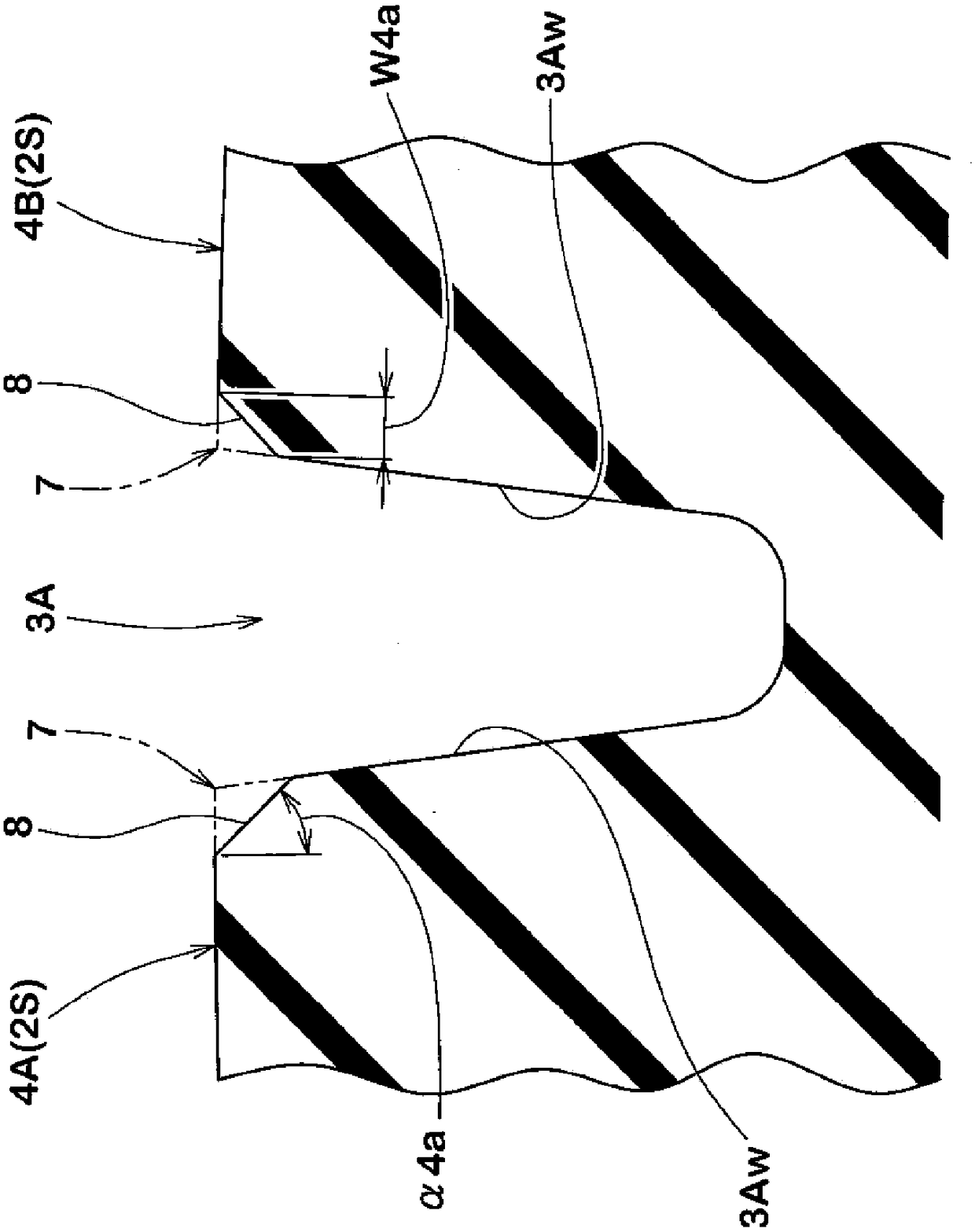
[0107] Angle α4a: 45 degrees, width W...


PUM


Abstract

The pneumatic tire (1) of the present invention has a pair of shoulder main grooves (3A) extending continuously in the tire circumferential direction on the tread portion (2) on the side closest to the tread contact end (2t). A pair of shoulder land portions (4A) defined between the shoulder main groove (3A) and the tread end (2t). At least one of the shoulder land portions (4A) has a plurality of shoulder lug grooves (5) and a plurality of shoulder sipes (6). The shoulder lug grooves (5) include a first shoulder lug groove (5A) extending from the tread contact end (2t) toward the tire axially inner side and terminating without reaching the shoulder main groove (3A). The shoulder sipes (6) include: a first tire extending from the axial inner end (5Ai) of the first shoulder lug groove (5A) to the inner side of the tire axial direction and communicating with the shoulder main groove (3A). A shoulder sipe (6A), and a second shoulder sipe (6B) intersecting the first shoulder sipe (6A) and extending in the tire circumferential direction.

Description

technical field [0001] The present invention relates to a pneumatic tire capable of improving uneven wear resistance while maintaining handling stability. Background technique [0002] Conventionally, there have been proposed pneumatic tires in which shoulder lug grooves are provided on the shoulder land part divided between the shoulder main groove and the tread ground edge, and the shoulder lug grooves extend from the tread ground edge to the tire axis. It extends inward and ends without reaching the shoulder main groove (see, for example, Patent Document 1 below). Such a pneumatic tire can increase the circumferential rigidity of the shoulder land portion, and thus can improve steering stability. [0003] Patent Document 1: Japanese Patent Application Laid-Open No. 2013-139194 [0004] However, in the shoulder land portion as described above, the rigidity at the inner end side of the shoulder lug groove in the tire axial direction is relatively increased, and a large di...

Claims


Application Information

Patent Timeline
Patent Type & Authority Patents(China)
IPC IPC(8): B60C11/12B60C11/01B60C11/03
CPCB60C11/0306B60C11/1392B60C11/0304B60C2011/0388B60C2011/1209B60C2011/1254B60C2011/0381B60C2011/0383B60C11/1281B60C2011/0334B60C2011/0341B60C2011/0358B60C2011/039B60C2011/1245B60C11/0327B60C11/1236B60C11/1307
Inventor 竹本义明
Owner SUMITOMO RUBBER IND LTD
Learn More