pneumatic tire

A pneumatic tire and tire technology, applied in tire parts, tire tread/tread pattern, transportation and packaging, etc., can solve the problems of low rigidity, partial wear, etc., to improve the circumferential rigidity of the tire, improve the axial direction of the tire Rigidity, the effect of improving rigidity

Inactive Publication Date: 2017-10-13
SUMITOMO RUBBER IND LTD
View PDF1 Cites 0 Cited by
  • Summary
  • Abstract
  • Description
  • Claims
  • Application Information

AI Technical Summary

Problems solved by technology

[0004] However, the rigidity of the concave portion depressed toward the center-of-gravity side of the block is low for the zigzag portion of the edge of the block
Therefore, the deformation of the block near the concave portion increases, so there is a tendency for partial wear to occur easily.

Method used


Image

  • pneumatic tire
  • pneumatic tire
  • pneumatic tire

Examples


Embodiment

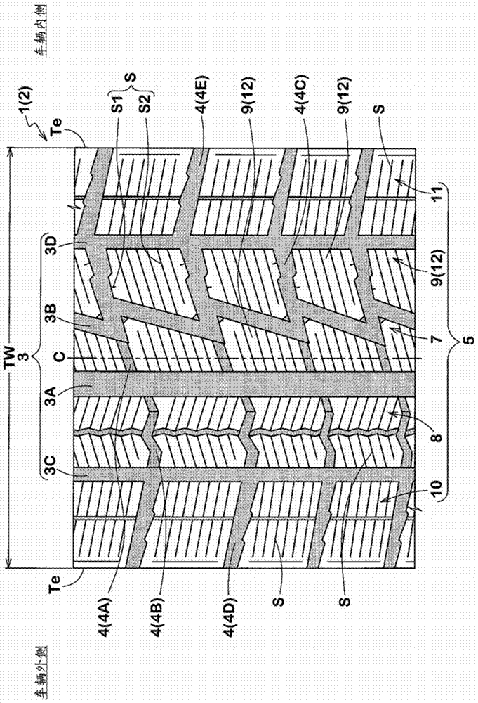
[0061] Based on the specifications in Table 1, a trial production with figure 1 A test tire (size: 195 / 65R15) with the basic pattern shown was used, and these properties were tested.

[0062] Each test method is as follows.

[0063]

[0064] Each test tire was installed on the all-wheel of a rear-wheel drive vehicle with a displacement of 2000cc with a rim (15×6.0J) and internal pressure (210kPa), and was driven by a driver on a test route on a snowy road. Steering stability performance on snowy roads is evaluated based on characteristics related to steering wheel responsiveness, rigidity, and grip evaluated by the driver's senses. The results are expressed as an index with 100 as the comparative example. The higher the value, the better.

[0065]

[0066] Each test tire was installed on the all-wheel of a rear-wheel drive vehicle with a displacement of 2000cc with a rim (15×6.0J) and an internal pressure (210kPa), and was driven by a driver on an icy road. The test ve...


PUM


Abstract

The present invention provides a pneumatic tire capable of further improving performance on icy and snowy roads and improving partial wear resistance. The pneumatic tire has a first pattern block (12) divided by a transverse groove (4) on the tread portion (2), the first pattern block includes a tread, a pattern block wall surface (13), and an edge (14), and the edge includes sawtooth shaped portion (18), the serrated portion includes a first edge (15), a second edge (16) connected to one end (15A) of the first edge, and a second edge (16) connected to the other end (15B) of the first edge Three edges, the other end is located closer to the center of gravity side of the first pattern block than one end, and the wall surface of the pattern block includes a first wall surface, a second wall surface, a third wall surface, and a fourth wall surface arranged between the first wall surface and the third wall surface. The wall surface and the fourth wall surface are formed in a substantially triangular shape surrounded by a first edge extending on the first wall surface, a second edge extending on the groove bottom, and a third edge extending on the third wall surface.

Description

technical field [0001] The present invention relates to a pneumatic tire having blocks defined by a plurality of lateral grooves in a tread portion. Background technique [0002] Conventionally, a pneumatic tire employing a tread pattern having a plurality of blocks in a tread portion has been proposed (see, for example, Patent Document 1 below). In order to improve the frictional force on icy road surfaces, the edges of the treads of the blocks include serrations, for example. [0003] Patent Document 1: Japanese Patent Laid-Open No. 2012-218651 [0004] However, the rigidity of the concave portion depressed toward the center-of-gravity side of the block is low for the zigzag portion of the edge of the block. Therefore, deformation of the block increases in the vicinity of the recessed portion, and thus partial wear tends to easily occur. Contents of the invention [0005] The present invention has been made in view of the above circumstances, and its main object is to...

Claims


Application Information

Patent Timeline
Patent Type & Authority Patents(China)
IPC IPC(8): B60C11/03B60C11/11
Inventor 末吉裕介
Owner SUMITOMO RUBBER IND LTD
Why Eureka
Try Eureka