A drilling tool

A cutting tool and drilling technology, which is applied in the manufacture of tools, drilling tool accessories, metal processing equipment, etc., can solve the problems of difficult to guarantee cutting accuracy, reduce manufacturing cost, and affect the cutting performance of tools, so as to improve the circumferential rigidity and reduce the Effect of cutting vibration and increasing drilling depth

Active Publication Date: 2022-05-24
ZHUZHOU CEMENTED CARBIDE CUTTING TOOLS CO LTD
View PDF0 Cites 0 Cited by
  • Summary
  • Abstract
  • Description
  • Claims
  • Application Information

AI Technical Summary

Problems solved by technology

However, the center drill point generally adopts mold pressing molding process, which is easy to produce deformation and cracks when sintering complicated large-scale products. Therefore, due to the restriction of the production process, the diameter of the drilling tool using the center drill point can only be less than 30mm.
[0004] Using a central drill point and two outer cutting inserts to form a cutting unit with a combined edge can greatly increase the diameter of the drilling tool, but the cutting overhang of this type of drilling tool is required to be more than 10 times the cutting diameter, and the clamping parts are made The cost is high, the cutting accuracy is difficult to guarantee, and the easily damaged area is generally concentrated in the part of the cutter body adjacent to the cutting area. Design the clamping part, the cutting part can be repeatedly installed on the clamping part, when the cutting part is damaged, only the cutting part needs to be replaced and the clamping part does not need to be replaced, which greatly reduces the manufacturing cost, but the drilling with split structure It is difficult to ensure the connection accuracy and rigidity of the tool, cutting parts and clamping parts, which greatly affects the cutting performance of the tool

Method used


Image

  • A drilling tool
  • A drilling tool
  • A drilling tool

Examples


Embodiment Construction

[0033] The present invention will be further described in detail below with reference to the accompanying drawings and specific embodiments.

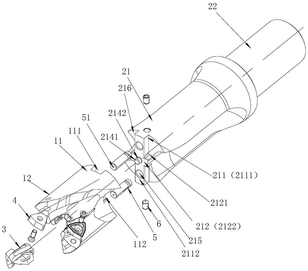
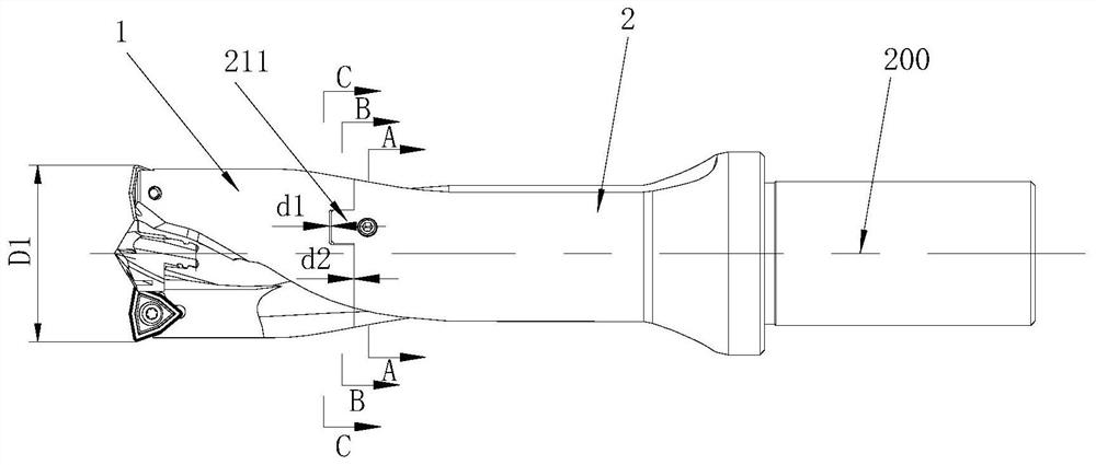
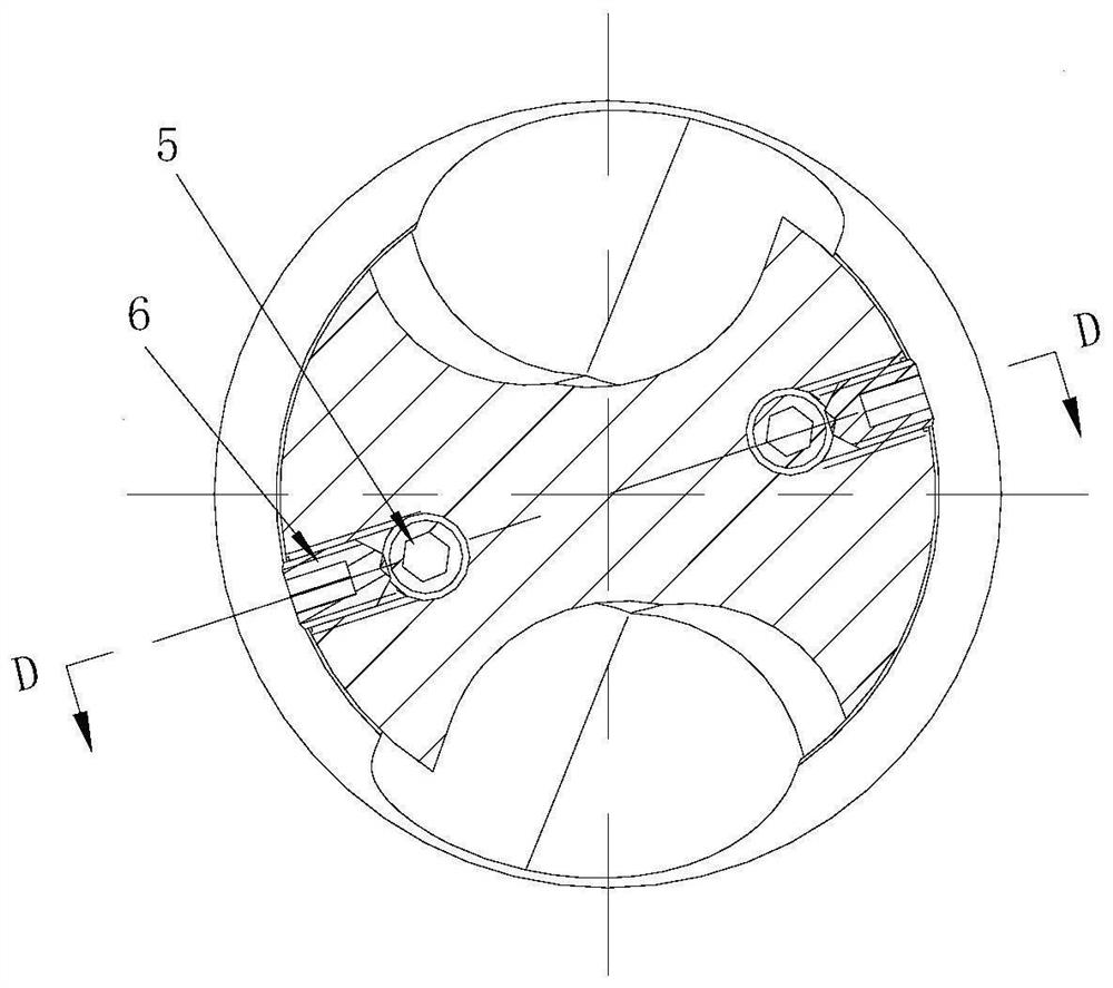
[0034] Figure 1 to Figure 8 An embodiment of the drilling tool of the present invention is shown, the drilling tool includes a cutting part 1, a clamping part 2, a center drill tip 3 and two outer cutting inserts 4, and the cutting part 1 is provided with a cutting interface The clamping part 11 and the cutting part 12, the clamping part 2 is provided with a clamping interface part 21 and a clamping part 22, the cutting interface part 11 can be repeatedly attached to and detached from the clamping interface part 21, the center drill tip 3 and the outer cutting insert 4 are respectively installed At the central and circumferential positions on the cutting portion 12, two outer cutting inserts 4 are respectively arranged on both sides of the central drill tip 3 to form a complete cutting unit with the central drill tip 3, and the cutting i...


PUM


Abstract

The invention discloses a drilling tool. Two outer cutting blades are respectively arranged on both sides of a central drill point to form a complete cutting unit with the central drill point. The cutting interface is provided with first clamping recesses intersecting each other. and the second clamping recess, the clamping interface is provided with a first clamping boss and a second clamping boss intersecting each other, the first clamping recess runs through the peripheral surface of the cutting interface, and the second clamping The bottom surface of the flute that runs through the cutting interface is recessed, the outer surface of the first clamping boss is smoothly connected with the peripheral surface of the clamping interface, and the outer surface of the second clamping boss is connected to the row of the clamping interface. The bottom surface of the chip flute is smoothly connected. When the cutting part is installed on the clamping part, the first clamping boss is placed in the first clamping recess, and the second clamping boss is placed in the second clamping recess. And cooperate to realize the circumferential positioning of the cutting part and the clamping part, the drilling tool of the present invention has the advantages of convenient assembly and disassembly, high positioning strength and precision.

Description

technical field [0001] The invention mainly relates to the field of metal cutting processing, in particular to a drilling tool. Background technique [0002] In drilling, in order to prolong the service life of the cutting part, more expensive cemented carbide or similar materials are usually used as tool materials. Such materials have the characteristics of high hardness and good wear resistance, but the processing is extremely difficult, which makes Drilling tool material costs and machining costs are high. [0003] At present, the commonly used drilling tools are generally assembled by a center drill tip and a clamping tool body. The center drill tip is made of hard alloy or similar material with high hardness and wear resistance, and the clamping tool body is made of Made of material with greater elasticity, after the center drill tip is damaged, it only needs to be replaced with a new center drill tip, thereby reducing the use cost of the drilling tool. However, the c...

Claims


Application Information

Patent Timeline
Patent Type & Authority Patents(China)
IPC IPC(8): B23B51/08
CPCB23B51/08
Inventor 江爱胜向良雄余仁超
Owner ZHUZHOU CEMENTED CARBIDE CUTTING TOOLS CO LTD
Why Eureka
Try Eureka