Modular drilling machining tool

A machining tool and modular technology, applied in the field of metal cutting, can solve the problems of high manufacturing cost of clamping parts, difficult to guarantee cutting accuracy, deformation and cracks, etc. to the rigid effect

Active Publication Date: 2021-03-09
ZHUZHOU CEMENTED CARBIDE CUTTING TOOLS CO LTD
View PDF10 Cites 2 Cited by
  • Summary
  • Abstract
  • Description
  • Claims
  • Application Information

AI Technical Summary

Problems solved by technology

However, the center drill point generally adopts mold pressing molding process, which is easy to produce deformation and cracks when sintering complicated large-scale products. Therefore, due to the restriction of the production process, the diameter of the drilling tool using the center drill point can only be less than 30mm.
[0004] Using a central drill point and two outer cutting inserts to form a cutting unit with a combined edge can greatly increase the diameter of the drilling tool, but the cutting overhang of this type of drilling tool is required to be more than 10 times the cutting diameter, and the clamping parts are made The cost is high, the cutting accuracy is difficult to guarantee, and the easily damaged area is generally concentrated in the part of the cutter body adjacent to the cutting area. Design the clamping part, the cutting part can be repeatedly installed on the clamping part, when the cutting part is damaged, only the cutting part needs to be replaced and the clamping part does not need to be replaced, which greatly reduces the manufacturing cost, but the drilling with split structure It is difficult to ensure the connection accuracy and rigidity of the tool, cutting parts and clamping parts, which greatly affects the cutting performance of the tool

Method used


Image

  • Modular drilling machining tool
  • Modular drilling machining tool
  • Modular drilling machining tool

Examples


Embodiment Construction

[0029] The present invention will be further described in detail below in conjunction with the accompanying drawings and specific embodiments.

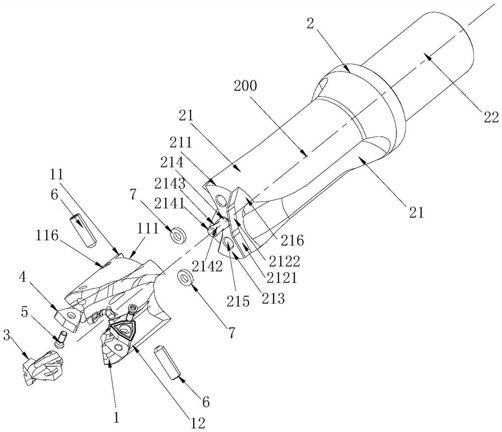
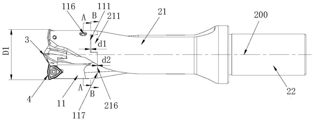
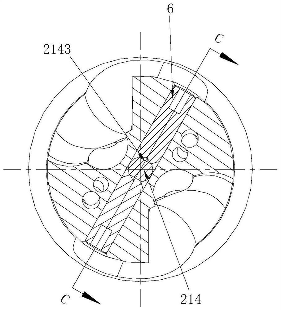
[0030] Figure 1 to Figure 6 An embodiment of the modular drilling tool of the present invention is shown, including a cutting part 1, a clamping part 2, a center drill tip 3 and two outer cutting inserts 4, and the cutting part 1 is provided with a cutting interface part 11 and the cutting part 12, the clamping part 2 is provided with a clamping interface part 21 and a clamping part 22, and the center drill point 3 and the outer cutting insert 4 are installed on the center and the circumferential position of the cutting part 12 respectively, and the two outer cutting The blade 4 is arranged on both sides of the center drill point 3 to form a complete cutting unit with the center drill point 3. The cutting interface part 11 is provided with a clamping recess 111, and the clamping interface part 21 is provided with a clamping boss 211....


PUM


Abstract

The invention discloses a modular drilling machining tool. The modular drilling machining tool comprises a cutting component, a clamping component, a center drill tip and two outer cutting blades, wherein the cutting component is provided with a cutting connector part and a cutting part, the clamping component is provided with a clamping connector part and a clamping part, the center drill tip andthe outer cutting blades are installed in the center and the circumferential position of the cutting part correspondingly, the two outer cutting blades are arranged on the two sides of the center drill tip to form a complete cutting unit with the center drill tip, a clamping concave part is arranged on the cutting connector part, a clamping boss is arranged on the clamping connector part, the clamping concave part penetrates through the circumferential face of the cutting connector part, the outer side face of the clamping boss is smoothly connected with the circumferential face of the clamping connector part, when the cutting component is installed on the clamping component in place, the clamping boss is arranged in the clamping recess and matched with the clamping recess to achieve circumferential positioning of the cutting component and the clamping component, and the modular drilling machining tool has the advantages of being convenient to assemble and disassemble, high in positioning strength and precision and the like.

Description

technical field [0001] The invention mainly relates to the field of metal cutting, in particular to a modular drilling tool. Background technique [0002] In drilling, in order to prolong the service life of the cutting part, relatively expensive cemented carbide or similar materials are usually used as tool materials. Such materials have the characteristics of high hardness and good wear resistance, but processing is extremely difficult, which makes Drilling tool material costs and machining costs are high. [0003] At present, the commonly used drilling tools are generally assembled by a center drill point and a clamping cutter body. The center drill point is made of hard alloy or similar material with high hardness and strong wear resistance, and the clamping cutter body is made of Made of materials with greater elasticity, only a new center drill tip needs to be replaced after the center drill tip is damaged, thereby reducing the cost of drilling tools. However, the ce...

Claims


Application Information

Patent Timeline
Patent Type & Authority Applications(China)
IPC IPC(8): B23B51/08
CPCB23B51/08
Inventor 江爱胜项兴东余仁超向良雄
Owner ZHUZHOU CEMENTED CARBIDE CUTTING TOOLS CO LTD
Why Eureka
Try Eureka