Widely-applied test tube rack

A technology of application scope and test tube rack, applied in the direction of test tube bracket/clamp, etc., can solve the problems of not draining the test tube, affecting the progress of the experiment, unstable placement of the test tube, etc., to achieve easy coordination, convenient operation, and simple production process. Effect

Inactive Publication Date: 2016-04-20
INST OF GEOCHEM CHINESE ACADEMY OF SCI
View PDF5 Cites 3 Cited by
  • Summary
  • Abstract
  • Description
  • Claims
  • Application Information

AI Technical Summary

Problems solved by technology

[0004] However, in practical applications, various tests and analyzes often require a variety of test tubes of different specifications to process a large number of experimental samples at the same time. Different measurement indicators may require different test tube specifications, and a large number of test tubes are required for batch experiments. It needs to use multiple test tube racks to complete, or need to place test tube racks with different specifications of test tubes, and if the test tube racks are placed too much, they are easy to be knocked down and damage the test tubes, and it also causes waste of test tube racks, which is inconvenient and affects the progress of the experiment; The test tube racks in the laboratory are different from the specifications of the test tubes, which will easily cause the test tubes to be placed unstable and broken, and many test tube racks do not have the function of draining the test tubes. In the case of drying, the draining efficiency is relatively slow, mainly because the test tube mouth is covered on the test tube rack, and the ventilation is not good, resulting in low draining efficiency

Method used


Image

  • Widely-applied test tube rack
  • Widely-applied test tube rack
  • Widely-applied test tube rack

Examples


Embodiment Construction

[0020] The present invention will be further described below in conjunction with the accompanying drawings and embodiments, but not as a basis for limiting the present invention.

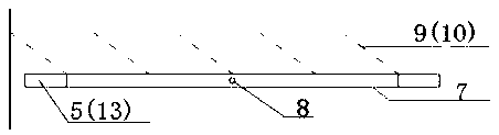
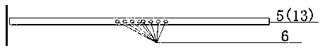
[0021] Example. A test tube rack with a wide range of applications, consisting of Figure 1-3 As shown, it includes a frame 1, and the frame 1 is sequentially provided with a top layer 2, an intermediate layer 3 and a bottom layer 4 from top to bottom; the top layer 2 includes a top layer network structure composed of top layer longitudinal lines 11 and top layer transverse lines 12; Layer 3 includes the middle layer network structure formed by the middle layer longitudinal line 9 and the middle layer transverse line 10, the two sides of the middle layer network structure are connected with the sliding rod 7 on the transverse connecting rod 5, and the two ends of the middle layer network structure Connect with the sliding rod 7 on the longitudinal connecting rod 13, the sliding rod 7 is set on the ...


PUM


Abstract

The present invention discloses a widely-applied test tube rack comprising a frame, the frame is provided, from top to bottom, with a top layer, a middle layer and a bottom layer, the top layer comprises a top layer mesh structure comprising a top layer transverse line and a top layer longitudinal line, the middle layer comprises a middle layer mesh structure comprising a middle layer transverse line and a middle layer longitudinal line, both sides of the intermediate layer transverse line are connected to a sliding rod on a transverse connecting rod, both ends of the intermediate layer longitudinal line are connected to a sliding rod on a longitudinal connecting rod, the sliding rods sleeve the transverse connecting rod and the longitudinal connecting rod, the transverse connecting rod and the longitudinal connecting rod are respectively provided with a scale hole, and the sliding rods are respectively provided with a fixing hole. The test tube rack has the advantages of being easy to use, easy to operate, capable of making full use of the advantages of the test tube rack and reducing laboratory test tube rack waste, material-saving, small in floor space, and the like.

Description

technical field [0001] The invention relates to a laboratory test tube rack, in particular to a laboratory test tube rack suitable for batch processing liquid to be tested and draining test tubes, easy to operate and wide in application range. Background technique [0002] The test tube rack is mainly used to place test tubes. It is a commonly used equipment in chemical and biological experiments, and is a must-have for every chemical and biological laboratory. With the rapid development of chemical, medical, and biological experiments at home and abroad, the market demand for experimental test tube racks is increasing, and new requirements are also generated for the materials and specifications of test tube racks. Existing test tube racks have many materials and styles, but the hole diameters on the test tube racks are fixed and cannot be adjusted. Some test tube racks even have special test tube holes, which are only suitable for test tubes of fixed specifications. [000...

Claims


Application Information

Patent Timeline
Patent Type & Authority Applications(China)
IPC IPC(8): B01L9/06
Inventor 陈佳张林蔡先立彭韬黎廷宇程安云
Owner INST OF GEOCHEM CHINESE ACADEMY OF SCI
Why Eureka
Try Eureka