
Stacking equipment positioning mechanism

A positioning mechanism and equipment technology, applied in the field of palletizing, can solve problems such as easy shaking or offset, and inaccurate stacking of goods, and achieve the effects of simple, convenient, stable, increased stability, convenient movement and positioning

Inactive Publication Date: 2019-04-16
合肥动联自动化科技有限公司
View PDF7 Cites 0 Cited by
  • Summary
  • Abstract
  • Description
  • Claims
  • Application Information

AI Technical Summary

Problems solved by technology

[0002] In the field of palletizing technology, it is necessary to stack the goods neatly together through the palletizer, so as to save the space for placing the goods and reduce the possibility of dumping the goods. When the palletizer is working, a transport trolley is generally placed under the rack. Then use the mechanical arm on the rack to stack the goods on the carrier. In order to facilitate the movement of the carrier, rollers are installed under the load. However, due to the function of the rollers, the goods are easy to shake or shift during the stacking process, causing the goods The code placement is not accurate enough

Method used


Image

  • Stacking equipment positioning mechanism
  • Stacking equipment positioning mechanism
  • Stacking equipment positioning mechanism

Examples


Embodiment Construction

[0026] The present invention will be described in detail below in conjunction with examples. Wherein the same components are denoted by the same reference numerals, it should be noted that the words "front", "rear", "left", "right", "upper" and "lower" used in the following description refer to In the directions in the drawings, the words "inner" and "outer" refer to directions toward or away from, respectively, the geometric center of a particular component.

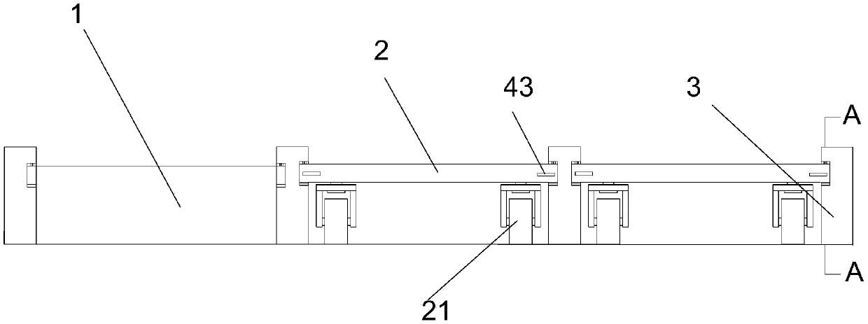
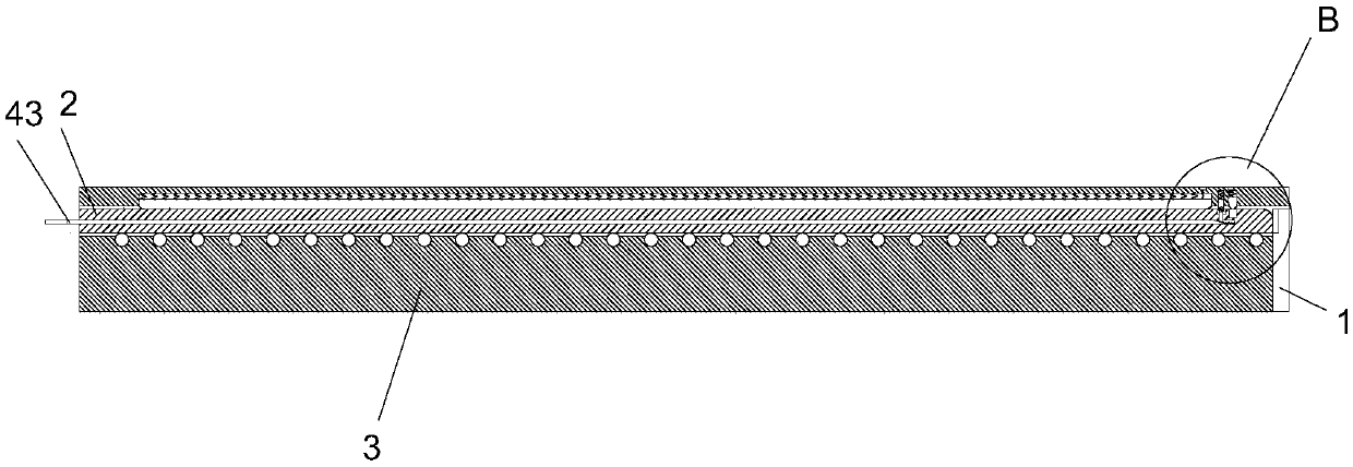
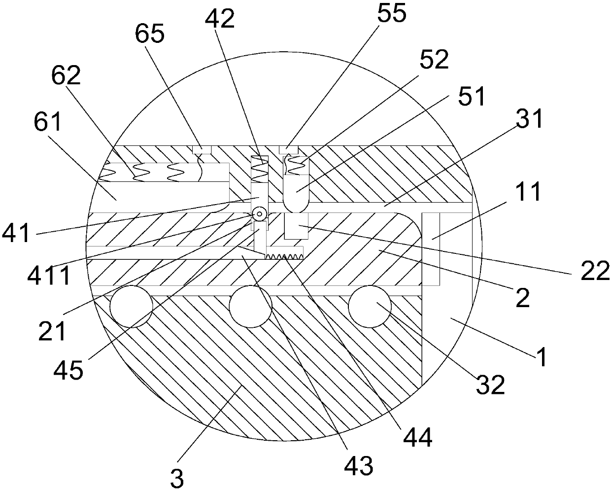
[0027] refer to figure 1 , figure 2 and image 3 As shown, a palletizing equipment positioning mechanism proposed by the present invention includes a first longitudinal baffle 1, a carrier 2, a positioning mechanism and a plurality of second longitudinal baffles 3, and the second longitudinal baffles 3 are installed on the first On the same side of the longitudinal baffles 1 and parallel to each other, an accommodation chamber for placing the carrier 2 is formed between any two adjacent second longitudinal baffles 3...


PUM


Abstract

The invention discloses a stacking equipment positioning mechanism. The stacking equipment positioning mechanism comprises a first longitudinal baffle, material carrying brackets, positioning mechanisms, and a plurality of second longitudinal baffles. The second longitudinal baffles are mounted on the same side of the first longitudinal baffle and are parallel. An accommodating chamber used for placing the material carrying brackets is formed between any two adjacent longitudinal baffles. First idler wheels are mounted on the lower parts of the material carrying brackets. Sliding grooves are formed in the second longitudinal baffles. The sliding grooves are used for the material carrying brackets to move in the direction being close to or away from the first longitudinal baffle. Each positioning mechanism comprises a positioning shaft, a first reset component, a push rod, a second reset component, and a supporting column. Positioning holes used for the positioning shafts to be clampedin are formed in the upper parts of the material carrying brackets. Oblique first planes are arranged on the lower parts of the supporting columns. Oblique second planes are arranged on the push rods.The stacking equipment positioning mechanism is easy to manufacture. Moving and positioning can be conveniently achieved by the material carrying brackets. Stability during material placing is effectively improved.

Description

technical field [0001] The invention relates to the technical field of palletizing, in particular to a positioning mechanism for palletizing equipment. Background technique [0002] In the field of palletizing technology, it is necessary to neatly stack the goods together through the palletizer, so as to save the space for placing the goods and reduce the possibility of dumping the goods. When the palletizer is working, a transport trolley is generally placed under the rack. Then use the mechanical arm on the rack to stack the goods on the carrier. In order to facilitate the movement of the carrier, rollers are installed under the load. However, due to the function of the rollers, the goods are easy to shake or shift during the stacking process, resulting in The code placement is not accurate enough. Contents of the invention [0003] In order to solve the technical problems existing in the background technology, the present invention proposes a positioning mechanism for ...

Claims


Application Information

Patent Timeline
Patent Type & Authority Applications(China)
IPC IPC(8): B65G57/00
CPCB65G57/00
Inventor 彭敏
Owner 合肥动联自动化科技有限公司
Learn More