
Exterior rearview mirror bracket for vehicle surround view system

A technology for exterior rearview mirrors and rearview mirrors, which is applied to vehicle components, optical observation devices, transportation and packaging, etc. It can solve problems such as blind spots, inability to guarantee vehicle safety, and inability of the vehicle surround view system to clearly reflect the surroundings of the vehicle. , to achieve the effect of no visual blind spots and real and reliable images

Active Publication Date: 2018-06-05
YINJIA ELECTRONICS TECH SHANGHAI CO LTD
View PDF5 Cites 0 Cited by
  • Summary
  • Abstract
  • Description
  • Claims
  • Application Information

AI Technical Summary

Problems solved by technology

In the prior art, when installing the vehicle-mounted surround view system, it is necessary to open a hole on the exterior rearview mirror bracket, and then assemble the camera in the hole. Such an operation is not only cumbersome, but also cannot guarantee that the installation angle of the camera can adapt to the vehicle-mounted surround view system. If the cameras on the left and right sides do not have a reasonable installation angle, there will be visual blind spots or image distortion in the surround view, so that the vehicle surround view system cannot clearly reflect the situation around the vehicle, and the safety of the vehicle cannot be guaranteed.

Method used


Image

  • Exterior rearview mirror bracket for vehicle surround view system
  • Exterior rearview mirror bracket for vehicle surround view system
  • Exterior rearview mirror bracket for vehicle surround view system

Examples


Embodiment Construction

[0015] In order to further illustrate the technical means and functions adopted by the present invention to achieve the intended invention purpose, the present invention will be described in detail below in conjunction with the accompanying drawings and preferred embodiments.

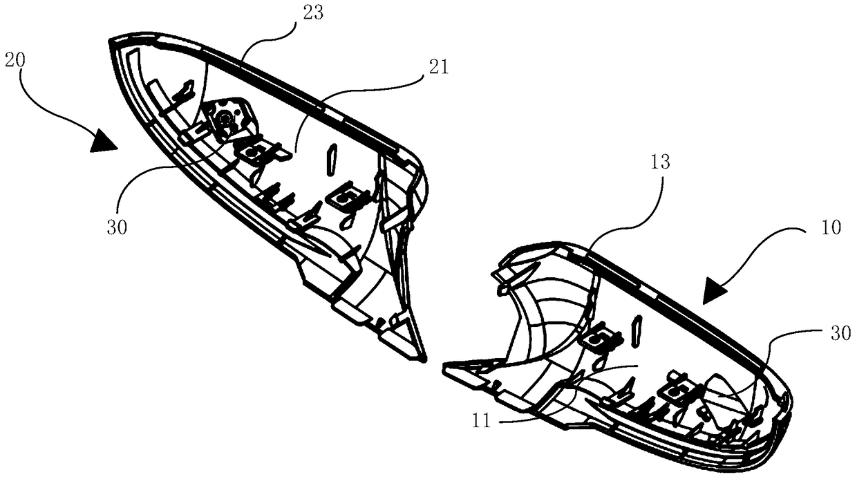
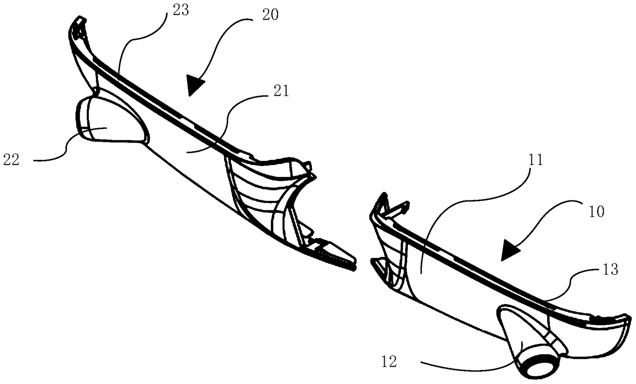
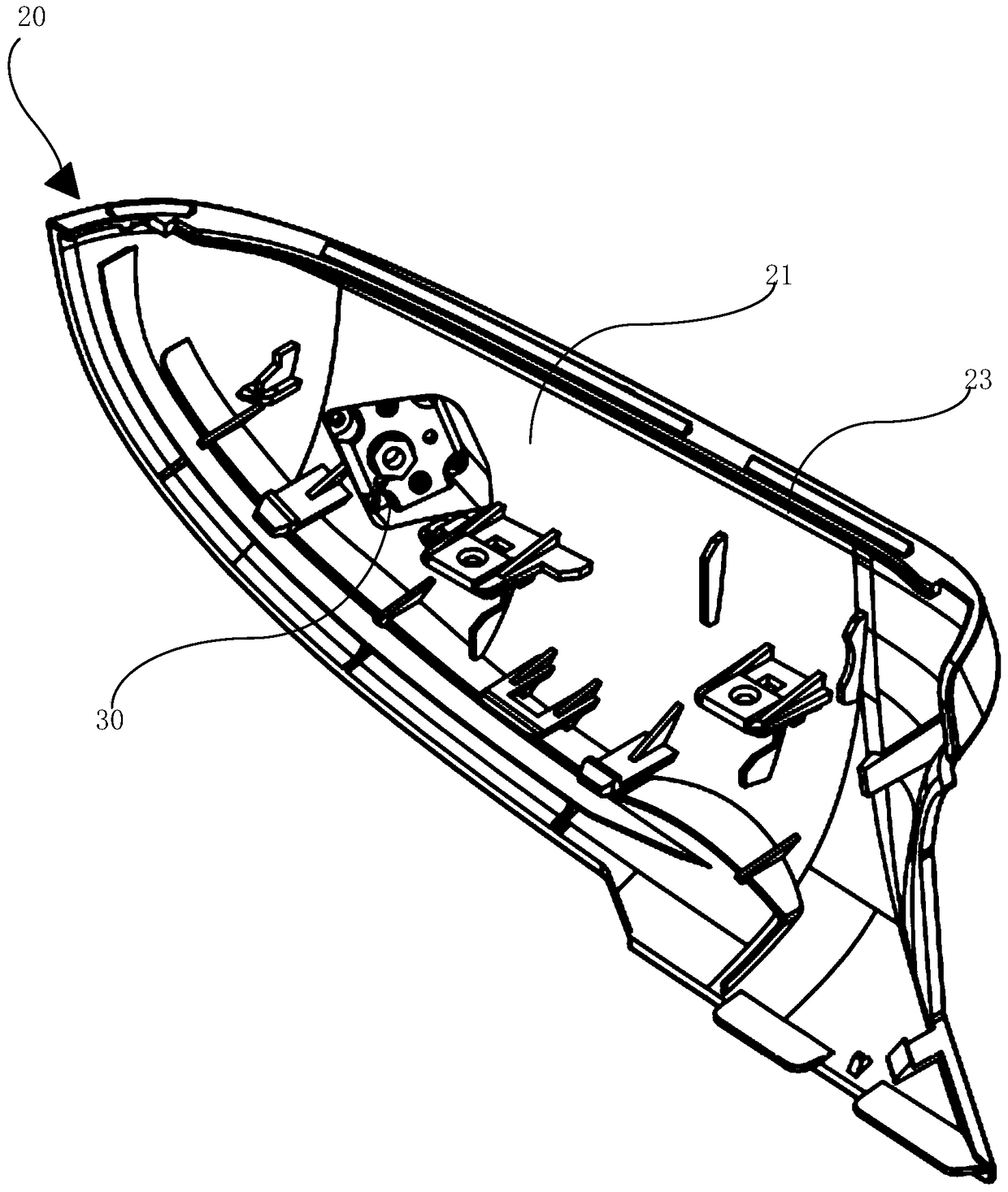
[0016] The invention provides an exterior rearview mirror bracket for a vehicle-mounted surround view system. When a side-view camera is installed on the exterior rearview mirror bracket, the exterior rearview mirror bracket can make the side-view camera have a reasonable installation angle, so that the side-view camera The captured images on both sides of the car body are horizontal, symmetrical and without distortion, so that the synthetic image of the vehicle surround view system is real and reliable, without visual blind spots. figure 1 Shown is a schematic structural view of an exterior rearview mirror bracket for a vehicle-mounted surround view system provided by an embodiment of the present invent...


PUM


Abstract

The invention relates to an exterior rearview mirror support for a vehicle-mounted all-round system. The exterior rearview mirror support comprises a support body and a camera installation hole formed in the support body, wherein a side-view camera is installed in the camera installation hole, when the side-view camera is installed in an installation hole of the rearview mirror support, the axis of a view angle center axis of the side-view camera is overlapped with that of the camera installation hole, when the exterior rearview mirror support is installed on a vehicle, the camera installation hole faces the ground and is inclined towards the tail direction of the vehicle, an angle formed between the projection of the center axis of the camera installation hole on a vertical plane in the length direction of the vehicle and the horizontal plane is 15 to 25 degrees, an angle formed between the projection of the center axis of the camera installation hole on the horizontal plane and the vertical plane on which the length direction of the vehicle is located is 85 degrees, and an angle formed between the forward direction of the side-view camera and the vertical direction in which a central point of the camera is located is inclined for 5 to 15 degrees towards the front part of the vehicle. The center axis of the camera installation hole has a specific angle, so that an image synthesized by the vehicle-mounted all-round system is real and reliable, and no blind spot exists.

Description

technical field [0001] The invention relates to the technical field of vehicle-mounted camera and display, in particular to an exterior rearview mirror bracket for a vehicle-mounted surround view system. Background technique [0002] With the development of technology, more and more vehicle-mounted surround view systems are applied to various vehicles. The vehicle-mounted surround-view system sets up 4 to 8 wide-angle cameras around the vehicle that can cover all fields of view around the vehicle. The road video image is processed into a 720-degree bowl-shaped composite image of the vehicle body, and the composite image is displayed on the screen of the center console, so that the driver can clearly check whether there are obstacles around the vehicle and understand the relative orientation and location of the obstacle. The distance is beneficial for the driver to park the vehicle and avoid obstacles. The car surround view system generally includes a front camera, a rear ca...

Claims


Application Information

Patent Timeline
Patent Type & Authority Patents(China)
IPC IPC(8): B60R1/06B60R1/00
CPCB60R1/00B60R1/06
Inventor 李竣岗
Owner YINJIA ELECTRONICS TECH SHANGHAI CO LTD
Learn More