
Hoisting system and hoisting construction method for large steel corridor trusses

A technology of steel corridors and trusses, which is applied in the processing of building materials, construction, building construction, etc., can solve the problems of large-scale steel corridors and trusses occupying a large area, the safety of well-controlled people cannot be guaranteed, and the balance is not easy, etc. To achieve the effect of convenient and effective control of the operation process, reasonable design and good stability

Inactive Publication Date: 2016-04-20
CHINA RAILWAY BEIJING ENG GRP CO LTD +1
View PDF5 Cites 27 Cited by
  • Summary
  • Abstract
  • Description
  • Claims
  • Application Information

AI Technical Summary

Problems solved by technology

[0004] The purpose of the present invention is to provide a hoisting system and hoisting construction method of a large-scale steel corridor truss to solve the problems in the prior art that the large-scale steel corridor truss occupies a large area, is heavy, has poor stability, and is difficult to perform hoisting construction , effectively solve the technical problem that the balance is difficult to control and the safety cannot be guaranteed during the hoisting process of large-scale steel corridor trusses

Method used


Image

  • Hoisting system and hoisting construction method for large steel corridor trusses
  • Hoisting system and hoisting construction method for large steel corridor trusses
  • Hoisting system and hoisting construction method for large steel corridor trusses

Examples


Embodiment Construction

[0062] Hereinafter, an embodiment of the hoisting system of the large-scale steel corridor truss and its hoisting construction method involved in the present invention will be described with reference to the accompanying drawings.

[0063] The examples described here are specific specific implementations of the present invention, and are used to illustrate the concept of the present invention. They are all explanatory and exemplary, and should not be construed as limiting the implementation of the present invention and the scope of the present invention. In addition to the embodiments described here, those skilled in the art can also adopt other obvious technical solutions based on the claims of the application and the contents disclosed in the description, and these technical solutions include adopting any obvious changes made to the embodiments described here. Replacement and modified technical solutions.

[0064] The accompanying drawings in this specification are schematic...


PUM


Abstract

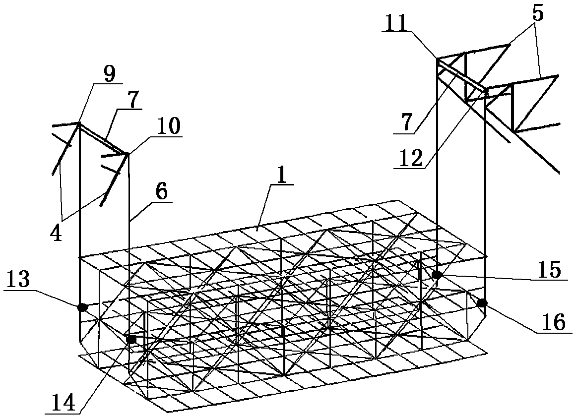
The invention discloses a hoisting system and a hoisting construction method for large steel corridor trusses. The hoisting system comprises lifting points, hanging points and jack lifting equipment. The jack lifting equipment is mounted between the lifting points and the hanging points, the lifting points comprise first lifting frames and second lifting frames, the first lifting frames are connected with first main structures, the second lifting frames are connected with second main structures, four embedded steel beams which have equal heights and are parallelly arranged are arranged in the two lifting frames of each lifting point, the lifting points are arranged at the ends of the embedded steel beams, two box-shaped brackets are respectively welded on two sides of each beam body of each lifting point, a jack is mounted on each box-shaped bracket, and each torsion-resistant steel beam is welded between the two corresponding box-shaped brackets on the inner sides of the beam bodies of the corresponding lifting points; the four corresponding hanging points which vertically correspond to the lifting points on a frame are arranged on each steel corridor truss, and steel strands penetrate the box-shaped brackets from top to bottom and are fixed by the aid of anchors after descending and penetrating the hanging points. Each large steel corridor truss can be synchronously lifted by the aid of the four corresponding hanging points during construction. The hoisting system and the hoisting construction method have the advantages that the hoisting system is reasonable in design and easy to operate, and problems of large occupied land areas, heavy dead weights and poor balance in existing large steel corridor truss hoisting procedures can be effectively solved by the aid of the hoisting system and the hoisting construction method.

Description

technical field [0001] The invention relates to the technical field of truss hoisting construction, in particular to a hoisting system and a hoisting construction method of a large-scale steel corridor truss. Background technique [0002] Corridor is a kind of complex high-rise building structure system. It generally refers to the connection between two or several high-rise buildings by overhead connectors to meet the requirements of building shape and use function. The connecting body is the corridor. Its span is several meters long, also has tens of meters long. There are one or several corridors arranged vertically along the building. On the one hand, the setting of the corridor is due to the requirements of architectural functions, and it can facilitate the connection between the two main structures. At the same time, the conjoined body has good lighting effects and a wide view, so it can be used as a sightseeing corridor or a leisure coffee shop; on the other hand, d...

Claims


Application Information

Patent Timeline
IPC IPC(8): E04G21/14
CPCE04G21/14
Inventor 闫慧清魏炜张超孙明华杨国栋孙荻
Owner CHINA RAILWAY BEIJING ENG GRP CO LTD
Learn More