Banknote-receiving device based on voltage-controlled rotating speed

A storage device and banknote technology, applied in the field of identification and storage of banknotes, can solve the problems of high product cost, inapplicability, increased cost, etc., and achieve the effect of low cost and simple structure

Inactive Publication Date: 2016-04-20
HUAZHONG AGRI UNIV
View PDF5 Cites 12 Cited by
  • Summary
  • Abstract
  • Description
  • Claims
  • Application Information

AI Technical Summary

Problems solved by technology

The coin-operating device on the car often uses an iron box, but there is no recognition and sorting function; this results in extra manpower to sort and store the banknotes after the daily operation, which not only causes inconvenience in use, but also causes waste of manpower
There are also some banknote processing institutions in the society, but because most of them use image processing technology and because the technology is immature, the designed devices are too large and costly, which is not conducive to small profit production
[0003] At present, many domestic bus companies use manual counting of banknotes after get off work, which not only wastes time, but also increases costs. Some banknotes that have been used for a long time will have an unpleasant smell and affect human health.
Most of the existing banknote storage and sorting mechanisms on the market use imaging technology, which results in high product costs and is not suitable for commercialization

Method used


Image

  • Banknote-receiving device based on voltage-controlled rotating speed
  • Banknote-receiving device based on voltage-controlled rotating speed

Examples


Embodiment Construction

[0036] Below in conjunction with accompanying drawing and embodiment this device is described in detail:

[0037] 1. The structure of the device

[0038] 1. Overall

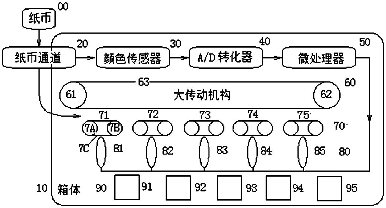
[0039] Such as figure 1 , the device includes the working object—banknote 00;

[0040] The entrance of the banknote channel 20 is provided outside the box body 10;

[0041] The main body of the banknote passage 20, the color sensor 30, the A / D converter 40, the microprocessor 50, the large transmission mechanism 60, the small transmission mechanism 70, the tension mechanism 80 and the storage box 90 are arranged in the box;

[0042] The color sensor 30 is arranged at the entrance of the banknote channel 20, facing the banknote 00;

[0043] A large transmission mechanism 60, a small transmission mechanism 70, a tensioning mechanism 80 and a storage box 90 are sequentially and correspondingly arranged under the banknote channel 20;

[0044] The color sensor 30 , the A / D converter 40 , the microprocessor 50 and...


PUM


Abstract

The invention discloses a banknote-receiving device based on voltage-controlled rotating speed and relates to a device for identifying and receiving banknotes. A banknote channel body, a color sensor, an A/D converter, a microprocessor, a large transmission mechanism, small transmission mechanisms, tensioning mechanisms, and receiving boxes are disposed in a box body. The color sensor is disposed on the inlet of a banknote channel and rightly faces the banknotes. The large transmission mechanism, the small transmission mechanisms, the tensioning mechanisms, and the receiving boxes are successively and correspondingly arranged under the banknote channel. The color sensor, the A/D converter, the microprocessor, and the tensioning mechanisms are successively connected, measure color signals of the banknotes, and gather different banknotes in different receiving boxes according to classifications. The banknote-receiving device may fast and accurately identify, classify, and count the banknotes, is simple in structure and low in cost, and can be widely used in small-profit enterprise. The receiving method based on voltage-controlled rotating speed and the color-based identifying principle are suitable for any apparatuses requiring identification and reception.

Description

technical field [0001] The invention relates to a device for identifying and storing banknotes, in particular to a banknote storage device based on voltage-controlled speed control. Background technique [0002] With the advancement of science and technology, modern society requires high efficiency, economy and convenience, which in turn puts forward higher requirements for existing facilities. For example, most of the current buses use self-service coin-operated mode in order to save labor costs. The coin-operating device on the car often uses an iron box, but it has no identification and sorting functions; this results in extra manpower to sort and store the banknotes after the daily operation, which not only causes inconvenience in use, but also causes waste of manpower. There are also some banknote processing institutions in the society, but because most of them use image processing technology and because the technology is immature, the designed device is too large and ...

Claims


Application Information

Patent Timeline
Patent Type & Authority Applications(China)
IPC IPC(8): G07D11/00
CPCG07D11/165
Inventor 介邓飞刘媛媛范潇赵杰安炳和
Owner HUAZHONG AGRI UNIV
Why Eureka
Try Eureka