
Light-emitting key

A key and light-emitting surface technology, applied in computing, electrical components, legends, etc., can solve the problems of dim light transmission area of ​​the keycap, too large distance difference, inconsistent brightness of light transmission effect, etc., to achieve long battery life time, reduce Power consumption and overall thickness reduction effect

Active Publication Date: 2016-04-20
DARFON ELECTRONICS (SUZHOU) CO LTD +1
View PDF3 Cites 6 Cited by
  • Summary
  • Abstract
  • Description
  • Claims
  • Application Information

AI Technical Summary

Problems solved by technology

[0003] However, the setting of the backlight module will cause the overall thickness of the luminous keyboard to be unable to be reduced, and the backlight module often has a large difference in the distance between the light source and different keys, which makes the brightness of the light transmission effect of each light-transmitting keycap on the luminous keyboard significantly inconsistent. , for example: the light-transmitting area of ​​the keycap near the light source is very bright, while the light-transmitting area of ​​the keycap around the keyboard far from the light source is very dim
Therefore, the light source should provide enough light energy, so that the emitted light can pass through the light guide plate and be transmitted to the bottom of the light-transmitting keycap far away from the light source, so that the light-transmitting area of ​​the keycap far away from the light source can still maintain enough light. Brightness, so the power and hardware specifications required by the light source cannot be reduced

Method used


Image

  • Light-emitting key
  • Light-emitting key
  • Light-emitting key

Examples


Embodiment Construction

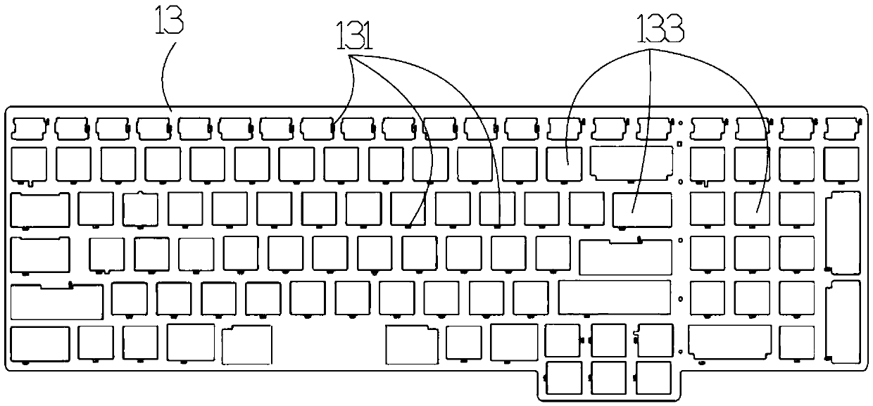
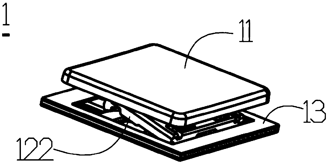
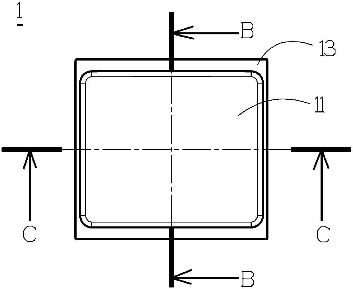
[0075] The directional terms mentioned in the following embodiments, such as: up, down, left, right, front or back, etc., are only directions referring to the attached drawings. Accordingly, the directional terms are used to illustrate and not to limit the invention. The present invention provides a light-emitting button, which can be used in a light-emitting keyboard, provides a dedicated light source for the light-transmitting keycap, and sets a light source on the side below the light-transmitting keycap, thereby omitting the setting of a backlight module and reducing the overall thickness of the light-emitting keyboard. In addition, since the light source does not need to irradiate multiple light-transmitting keycaps, the power and hardware specifications required by the light source do not need to be too high. In this way, the competitiveness of the light-emitting keyboard can be greatly improved. For the main technical idea of ​​the light-emitting button of the present i...


PUM


Abstract

The invention relates to a light-emitting key used in a light-emitting keyboard. A light source is arranged at a side under a light transmitting keycap; light rays emitted by the light source are emitted to a light transmitting area of the light transmitting keycap by a keycap connection mechanism or an elastic body of the light transmitting keycap through diffuse reflection or scattering. In this way, the light transmitting area of the light transmitting keycap can realize uniform light transmission, thus a backlight module is not required does not need to be arranged for the light-emitting keyboard, and the whole thickness of the light-emitting keyboard can be greatly reduced; in addition, arranging arrangement of a high-brightness light source is avoided, the light source electric energy consumption of the whole light-emitting keyboard can be greatly reduced, and a notebook computer using the light-emitting key is enabled to have longer battery endurance time.

Description

technical field [0001] The invention relates to a light-emitting key, in particular to a light-emitting key with a light source arranged on the lower side of a light-transmitting key cap. Background technique [0002] Due to the gradual popularization of luminous keyboards, users have increasingly strict requirements on the light transmission area of ​​luminous keyboards. At present, luminous keyboards will be equipped with a backlight module, which contains less than 15 LED light sources and a light guide plate ( lightguide), use the light guide plate to receive the light emitted by these LED light sources, and transmit the light to the bottom of each light-transmitting keycap on the luminous keyboard, and then use the scattering points on the light guide plate to extract light upward to each light-transmitting keycap The light-transmitting area of ​​the keycap. [0003] However, the setting of the backlight module will cause the overall thickness of the luminous keyboard ...

Claims


Application Information

Patent Timeline
IPC IPC(8): H01H13/83
CPCH01H13/83H01H2219/036H01H2231/002
Inventor 何信政许文明刘信鸿陈志宏
Owner DARFON ELECTRONICS (SUZHOU) CO LTD
Learn More