Clamping tool for machining motor case

A casing and fixture technology, applied in the manufacture of motor generators, electrical components, electromechanical devices, etc., can solve the problems of motor stator deformation, motor casing deformation, affecting the assembly of motor casing and motor end cover, etc., to ensure normal operation effect

Active Publication Date: 2016-04-20
上海雷祥压铸有限公司
View PDF7 Cites 5 Cited by
  • Summary
  • Abstract
  • Description
  • Claims
  • Application Information

AI Technical Summary

Problems solved by technology

At present, the motor casing is usually fixed by expanding the motor stator with the inner support fixture, and when the inner support fixture expands the motor stator, the motor stator will be slightly deformed, so that the motor casing will be slightly deformed, thus Affect the assembly between the motor casing and the motor end cover

Method used


Image

  • Clamping tool for machining motor case
  • Clamping tool for machining motor case

Examples


Embodiment Construction

[0017] The present invention will be described in further detail below in conjunction with the accompanying drawings and specific embodiments.

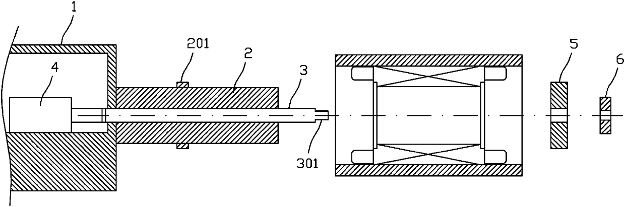
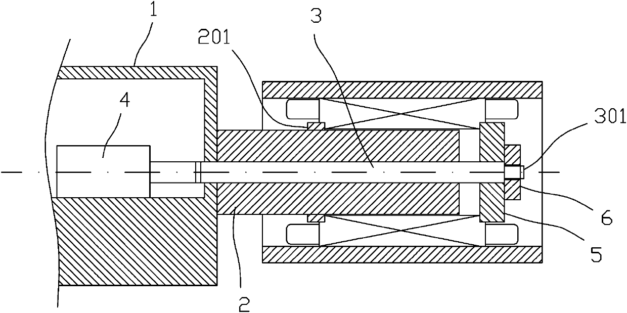
[0018] Depend on figure 1 , figure 2 As shown, the jig used for motor casing processing in the present invention includes a frame 1 , a positioning shaft 2 , a telescopic shaft 3 , a cylinder 4 , a pressing plate 5 and a nut 6 .

[0019] The positioning shaft 2 is arranged horizontally, and one end of the positioning shaft 2 is fixedly connected with the frame 1. The positioning shaft 2 is provided with an axially through center hole, and the outer peripheral wall of the positioning shaft 2 is provided with a radial convex ring 201. The distance between the other end face and the radial protruding ring 201 is less than the axial length of the motor stator, the outer diameter of the positioning shaft 2 is smaller than the aperture of the stator inner hole of the motor stator in the motor casing to be processed, and the positioning sh...


PUM


Abstract

The invention discloses a clamping tool for machining a motor case, and the tool clamps an end face of a motor stator in the motor case, so as to fix a motor and to machine the end face of the motor case. The tool can prevent the motor state from being expanded by supporting, and prevents the motor case from deforming.

Description

technical field [0001] The invention relates to a fixture used for machining a motor casing. Background technique [0002] When processing the motor, after the motor stator is assembled into the motor casing, it is necessary to process notches at both ends of the motor casing to facilitate the assembly between the motor end cover and the motor casing. Before machining the spigot, the motor casing needs to be clamped and fixed, and then the end face of the motor casing is milled so that the spigot is processed on the end face of the motor casing. At present, the motor casing is usually fixed by expanding the motor stator with the inner support fixture, and when the inner support fixture expands the motor stator, the motor stator will be slightly deformed, so that the motor casing will be slightly deformed, thus Affect the assembly between the motor casing and the motor end cover. Contents of the invention [0003] The technical problem to be solved by the present inventio...

Claims


Application Information

Patent Timeline
Patent Type & Authority Applications(China)
IPC IPC(8): H02K15/14
CPCH02K15/14
Inventor 王奇峰许海波
Owner 上海雷祥压铸有限公司
Why Eureka
Try Eureka