Method, device and system for controlling compressor

A technology of control algorithm and control circuit, which is applied in the field of compressor control, can solve the problems of high voltage ripple, lower system response speed, drop, etc., and achieve reduced input power ripple, high voltage ripple, and reduced energy storage capacitance. Effect

Active Publication Date: 2016-04-20
GREE ELECTRIC APPLIANCES INC
View PDF4 Cites 20 Cited by
  • Summary
  • Abstract
  • Description
  • Claims
  • Application Information

AI Technical Summary

Problems solved by technology

[0003] 1. Although the purpose of overvoltage protection can be achieved, due to the judgment of the Q-axis current compensation value, the calculation is complicated, which increases the running time of the processor and reduces the response speed of the system
[0004] 2. Although the electronic circuit can be installed inside the motor to achieve mechatronics, it is not conducive to the maintenance of circuit components and motor parts in the later stage, and due to the corrosion inside the compressor, it cannot be used on the variable frequency drive system of the air conditioner external unit. application
However, it cannot solve the problem of bus voltage drop caused by replacing electrolytic capacitors with film capacitors, and cannot guarantee the smooth operation of the motor
[0006] Aiming at the technical problem of high voltage ripple in the electrolytic capacitor motor drive circuit in the prior art, no effective solution has been proposed yet

Method used


Image

  • Method, device and system for controlling compressor
  • Method, device and system for controlling compressor
  • Method, device and system for controlling compressor

Examples


Embodiment 1

[0029] According to an embodiment of the present invention, an embodiment of a method for controlling a compressor is provided. It should be noted that the steps shown in the flow chart of the accompanying drawings can be executed in a computer system such as a set of computer-executable instructions, Also, although a logical order is shown in the flowcharts, in some cases the steps shown or described may be performed in an order different from that shown or described herein.

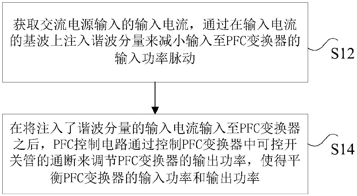
[0030] figure 1 is a flowchart of a method for controlling a compressor according to an embodiment of the present invention, such as figure 1 As shown, the method includes the following steps:

[0031] Step S12, obtain the input current input by the AC power supply, and reduce the input power pulsation input to the PFC converter by injecting harmonic components on the fundamental wave of the input current, wherein the harmonic components include at least: third harmonic components and / or or the fifth ...

Embodiment 2

[0138] According to an embodiment of the present invention, an embodiment of a device for controlling a compressor is provided, such as Figure 6 As shown, the device includes: an acquisition module 61 and an adjustment module 63 .

[0139] Wherein, the obtaining module 61 is used to obtain the input current input by the AC power supply, and reduce the input power pulsation input to the PFC converter by injecting harmonic components on the fundamental wave of the input current, wherein the harmonic components include at least: the third harmonic wave components and / or fifth harmonic components.

[0140] The adjustment module 63 is used to adjust the output power of the PFC converter by controlling the on-off of the controllable switch in the PFC converter after inputting the input current injected with harmonic components into the PFC converter, so as to balance the PFC The input power and output power of the converter.

[0141] Specifically, the above PFC converter may be a...

Embodiment 3

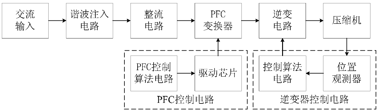
[0145] According to an embodiment of the present invention, a system embodiment for controlling a compressor is provided, such as Figure 7 As shown, the system includes: a harmonic injection circuit 71 , a PFC converter 73 , a PFC control circuit 75 and an AC power supply 77 .

[0146] Wherein, the harmonic injection circuit 71 is connected with the AC power supply 77, and is used to obtain the input current input by the AC power supply, and reduce the input power pulsation input to the PFC converter by injecting harmonic components on the fundamental wave of the input current, wherein , the harmonic component at least includes: the third harmonic component and / or the fifth harmonic component.

[0147] The PFC converter 73 is connected to the harmonic injection circuit 71, and is used to obtain an input current injected with a harmonic component.

[0148] Specifically, the above PFC converter may be a Boost type APFC (Active Power Factor Correction) converter.

[0149] The ...


PUM


Abstract

The invention discloses a method, device and system for controlling a compressor. The method comprises the steps that input current input by an alternating current power source is obtained and input power pulse input to a PFC converter is reduced, wherein harmonic components at least include triple frequency harmonic components and/or quintuple harmonic components; after the input current into which the harmonic components are injected is input to the PFC converter, a PFC control circuit adjusts output power of the PFC converter by controlling on-off of a controllable switching tube in the PFC converter, so that the input power and the output power of the PFC converter are balanced. The technical problem that voltage ripples of a motor drive circuit are high due to the fact that no electrolytic capacitor exists in the prior art is solved.

Description

technical field [0001] The present invention relates to the field of compressor control, in particular, to a method, device and system for controlling a compressor. Background technique [0002] In order to replace electrolytic capacitors with small-volume and low-cost film capacitors, the motor drive system without electrolytic capacitors in the prior art has the following disadvantages: [0003] 1. Although the purpose of overvoltage protection can be achieved, the calculation is complicated due to the judgment of the Q-axis current compensation value, which increases the running time of the processor and reduces the response speed of the system. [0004] 2. Although the electronic circuit can be installed inside the motor to achieve mechatronics, it is not conducive to the maintenance of circuit components and motor parts in the later stage, and due to the corrosion inside the compressor, it cannot be used on the variable frequency drive system of the air conditioner exte...

Claims


Application Information

Patent Timeline
Patent Type & Authority Applications(China)
IPC IPC(8): H02M1/12H02M1/42H02P27/00
CPCH02M1/12H02M1/42H02P27/00Y02B70/10
Inventor 刘玲张东盛刘亚祥程海珍苏勇雪区均灌王长恺
Owner GREE ELECTRIC APPLIANCES INC
Why Eureka
Try Eureka