
Multi-nozzle balanced flow meter

A balanced flow and multi-nozzle technology, which is applied to the volume/mass flow generated by mechanical effects, and the detection of fluid flow by measuring pressure difference, etc., can solve the problem of limited flow measurement range, high installation conditions, narrow measurement range, etc. problem, to achieve the effect of shortening requirements, saving operating energy costs, reducing turbulent shear force and eddy current formation

Inactive Publication Date: 2016-04-27
江苏华海测控技术有限公司
View PDF6 Cites 12 Cited by
  • Summary
  • Abstract
  • Description
  • Claims
  • Application Information

AI Technical Summary

Problems solved by technology

The differential pressure flowmeter is an instrument that measures the flow rate based on the differential pressure generated by the flow detection part installed in the pipeline, the known fluid conditions and the geometric dimensions of the detection part and the pipeline; however, the measurement range of this differential pressure flowmeter The range is narrow, because the flow meter signal (differential pressure) has a square function relationship, which limits the range of flow measurement
At present, the most commonly used nozzle forms of nozzle flowmeters are standard nozzles, long-neck nozzles, Venturi nozzles, etc. These throttling forms generally have the following disadvantages: the repeatability and accuracy of measurement are at the general level of flowmeters, due to many factors The influence is intricate, and the accuracy is difficult to improve; the site installation conditions are relatively high, and a long straight pipe section is required, which is generally difficult to meet, and the pressure loss is relatively large

Method used


Image

  • Multi-nozzle balanced flow meter
  • Multi-nozzle balanced flow meter

Examples


Embodiment Construction

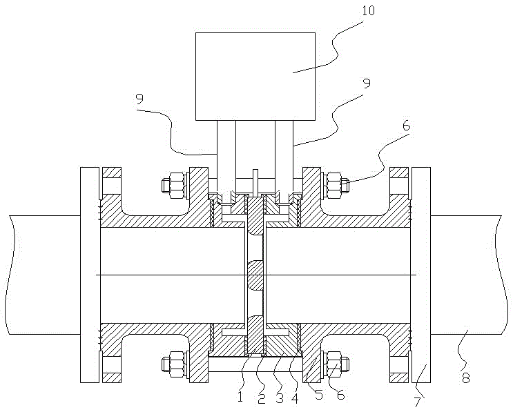
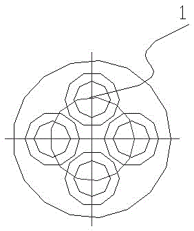
[0022] Such as Figure 1-2 As shown, the multi-nozzle balanced flowmeter includes a multi-nozzle balanced circular plate 1, an annular chamber 3, a connecting pipe 5 with a flange, a straight pipe section 8, a pressure-taking pipe 9 and a sensor 10. On the multi-nozzle balanced circular plate 1 A plurality of nozzles are regularly and uniformly arranged, and positioning grooves and pressure-taking holes are set on the ring chamber 3. The multi-nozzle balance circular plate 1 is clamped between the two ring chambers 3 through the positioning grooves. The connecting pipes 5 of the flanges are respectively located outside the two annular chambers 3 and are connected into one body by stud bolts 6. The straight pipe section 8 is installed on the connecting pipes 5 with flanges through the connecting flange 7, and the pressure-taking holes of the annular chambers 3 are welded. The pressure-taking pipe 9 and the sensor 10 welded on the pressure-taking pipe 9 form a multi-nozzle balan...


PUM


Abstract

The invention discloses a multi-nozzle balanced flow meter, comprising a multi-nozzle balanced circular plate (1), annular chambers (3), connection pipes (5) with flanges, a straight pipe section (8), pressure tapping pipes (9) and a sensor (10), wherein the multi-nozzle balanced circular plate (1) is provided with multiple nozzles in regular and uniform distribution, the annular chambers (3) are provided with positioning grooves and pressure tapping holes, the multi-nozzle balanced circular plate (1) is clamped between the two annular chambers (3) by the positioning grooves, the connection pipes (5) with the flanges are respectively located at the outer sides of the two annular chambers (3) and are connected into a whole by studs (6), the connection pipes (5) with the flanges are provided with the straight pipe section (8) by a connection flange, the pressure tapping pipes (9) are welded on the pressure tapping holes of the annular chambers (3), and the sensor (10) is welded on the pressure tapping pipes (9). The flow meter is wider in measurement range, higher in measurement accuracy, short in the straight pipe section, low in blocking possibility, more convenient to use, high in interchangeability with other flow meters, and longer in service life.

Description

technical field [0001] The invention relates to a measuring device for fluid flow in pipelines, in particular to a multi-nozzle balanced flowmeter. Background technique [0002] Now, the engineering of all walks of life pays special attention to accurate measurement, especially the flow measurement of the fluid in the pipeline of the fluid engineering layout adopts the flow meter. Differential pressure flowmeter occupies the forefront of flowmeter application due to its mature technology, simple structure, stability and reliability, and wide application surface. The differential pressure flowmeter is an instrument that measures the flow rate based on the differential pressure generated by the flow detection part installed in the pipeline, the known fluid conditions and the geometric dimensions of the detection part and the pipeline; however, the measurement range of this differential pressure flowmeter The range is narrow, because the flow meter signal (differential pressur...

Claims


Application Information

Patent Timeline
IPC IPC(8): G01F1/36G01F1/42
CPCG01F1/36G01F1/42
Inventor 周启全
Owner 江苏华海测控技术有限公司
Learn More