Power system fault diagnosis method

A technology of fault diagnosis and power system, applied in the direction of instruments, data processing applications, resources, etc.

Inactive Publication Date: 2016-04-27
谭焕玲
View PDF2 Cites 3 Cited by
  • Summary
  • Abstract
  • Description
  • Claims
  • Application Information

AI Technical Summary

Problems solved by technology

The same problem also exists in a

Method used


Image

  • Power system fault diagnosis method
  • Power system fault diagnosis method

Examples


Embodiment 1

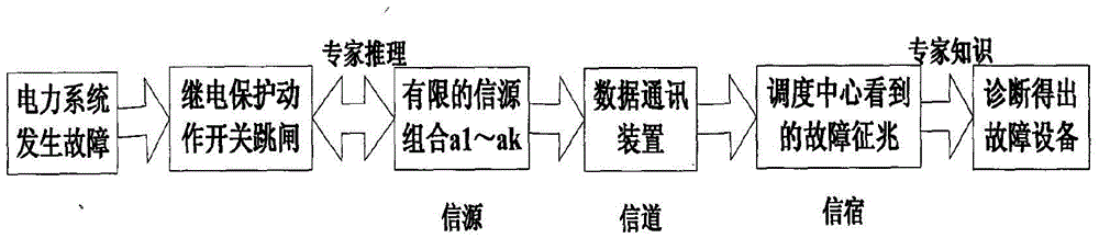
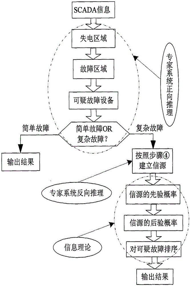
[0029] like Figure 1-2 As shown, a power system fault diagnosis method, first establishes the fault diagnosis information transmission model of the actual channel, according to the blackout area where the power system fails, uses the expert system to obtain all possible faulty equipment through forward reasoning, and then assumes When a suspicious device fails, reversely deduce the corresponding switch and protection action state, and obtain all possible sources in the actual communication; finally, combine the protection, the probability of refusal of the switch and the prior probability of equipment failure to calculate the source of the source. Information or prior probability, so that the uncertainty in the fault process is included in the source. In the actual SCADA system, the symptom information seen by the dispatch center is a set of data sequences composed of the protection and the action status of the switch. In this way, the conditional self-information of the sour...


PUM


Abstract

The present invention provides a power system fault diagnosis method. According to the method, the positive and negative inference of an expert system is used to determine a possible signal source, a signal source combination set is very limited, and the designation of all signal sources is based on a fault assumption and is substantially free from the influence of the failure sign received by a remote signal, the uncertain conditions of the protection refuse operation in the time of a failure, a switch refuse operation, a wrong operation and the like can be counted, and the various uncertainty problems of remote signal loss, wrong and the like in an actual channel (a motion channel) can be processed. The advantages of the expert system and an information theory are comprehensively used by an algorithm, and a practical requirement is basically satisfied.

Description

technical field [0001] The invention relates to the field of power system fault diagnosis, and more specifically, to a method for power system fault diagnosis. Background technique [0002] There is uncertainty in the power system fault process itself, which is mainly caused by protection or circuit breaker malfunction, refusal to operate, telecontrol information communication error and other factors. When the fault symptom signal can only be obtained through the SCADA (Data Acquisition and Monitoring) system, the uncertainty in the grid fault diagnosis is more obvious, which affects the real-time diagnosis of the grid fault. Both Bayesian network and information theory are based on probability theory, which can quantify the uncertainty of fault information. [0003] However, the fault diagnosis method based on the Bayesian network needs a large number of complete actual fault samples for training to improve the diagnostic accuracy. Moreover, the existing fault diagnosis me...

Claims


Application Information

Patent Timeline
IPC IPC(8): G06Q10/06G06Q50/06
CPCG06Q10/06G06Q50/06
Inventor 谭焕玲
Owner 谭焕玲
Why Eureka
Try Eureka