
Knee joint brace enabling three-dimensional movement

A technology for assistive devices and knee joints, applied in the directions of knee joints, elbow joints, joint implants, etc., can solve the problems that knee joint assistive devices cannot smoothly share the body load, the knee joint is twisted, and cannot be closely attached, etc., so as to achieve smooth sharing. The effect of body load

Active Publication Date: 2016-04-27
AJOU UNIV IND ACADEMIC COOP FOUND
View PDF9 Cites 0 Cited by
  • Summary
  • Abstract
  • Description
  • Claims
  • Application Information

AI Technical Summary

Problems solved by technology

[0005] However, in the auxiliary device for distributing the load of the knee joint disclosed in the Korean Patent Laid-Open No. 10-1110075, the attachment surface of the distal femur and the attachment surface of the proximal tibia to which the auxiliary device is to be fixed are not parallel to each other. In some cases, there are the following problems: the attachment surface of the femur cannot be in close contact with the lower surface of the femur side frame of the auxiliary device, or the attachment surface of the tibia cannot be in close contact with the lower surface of the tibial side frame of the auxiliary device, resulting in auxiliary The attachment of the appliance becomes unstable, or the knee is twisted, resulting in limited knee extension and flexion
Also, if the shape of the femur and tibia is abnormal so that the attachment surface of the auxiliary device of the distal femur and the attachment surface of the proximal tibia cannot be located on the same plane, the femoral side frame or the tibial side frame will be in a certain position. Since one side is not fixed to the distal femur or the proximal tibia, there is a risk that the knee assist device may not be able to share the body load smoothly.

Method used


Image

  • Knee joint brace enabling three-dimensional movement
  • Knee joint brace enabling three-dimensional movement
  • Knee joint brace enabling three-dimensional movement

Examples


Embodiment Construction

[0030] The above objects, features, and advantages will become more apparent through the following embodiments associated with the accompanying drawings. Specific structural and functional descriptions are only shown for illustrating embodiments of concepts according to the present invention, embodiments according to concepts of the present invention can be implemented in various forms, and should not be construed as being limited to the embodiments of the present invention Examples described in the specification. Embodiments according to the concept of the present invention can be variously modified and have various forms, so specific embodiments are illustrated in the drawings and described in detail in the specification of the present invention. However, it is not intended to limit the embodiment according to the concept of the present invention to the specific disclosed form, but it should be understood that all changes, equivalents, and substitutes within the scope of the...


PUM


Abstract

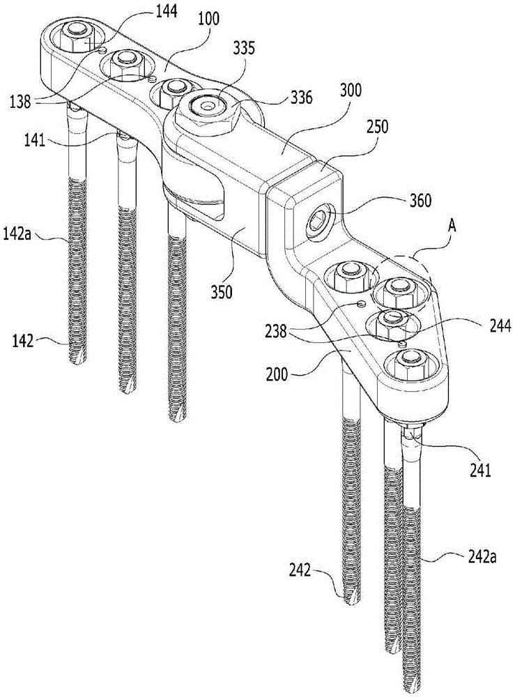
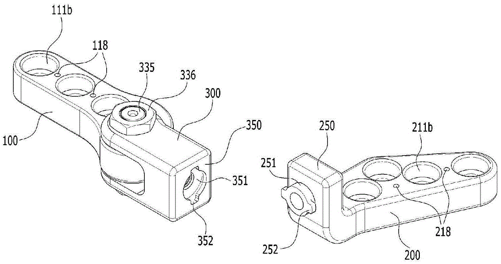
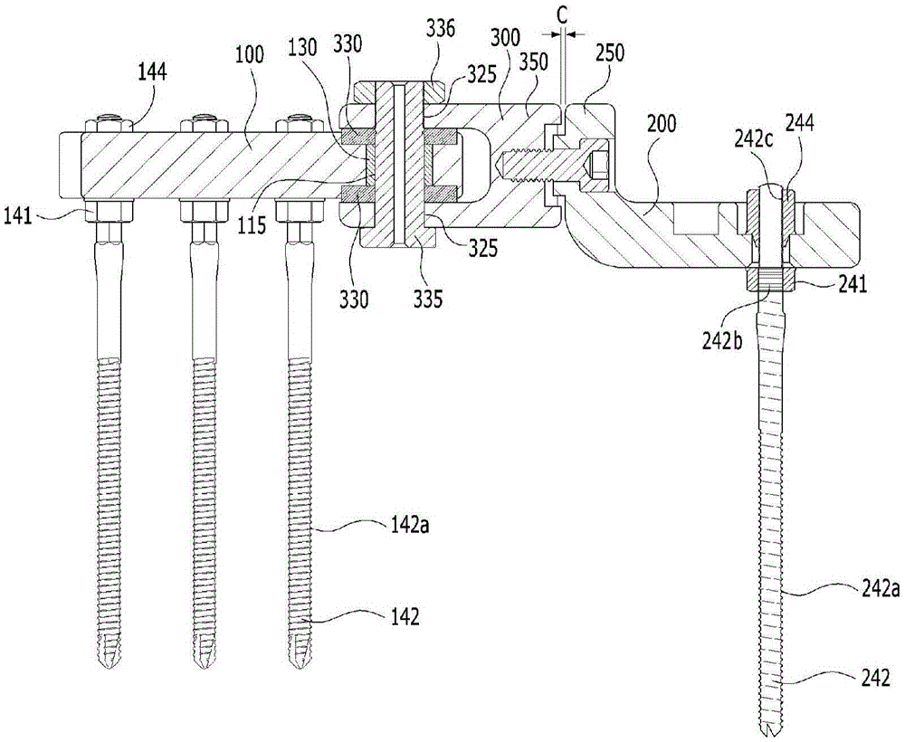
The present invention provides a knee joint brace in which frames of the knee joint brace can be mounted in close contact with the attachment surface of the femur and the attachment surface of the tibia even when the attachment surface of the femur and the attachment surface of the tibia are not parallel to each other, and the frames of the knee joint brace can be attached in close contact with the femur and the tibia whereby the body weight can be equally supported even when the brace-attached surface of the femur and the brace-attached surface of the tibia are not located on the same plane due to the abnormal shapes of the femur and the tibia. In addition, the knee joint brace according to the present invention is fixed between the femur and the tibia, and accordingly, has the advantage of enabling a three-dimensional movement of the knee joint of a surgical patient, etc. by assisting the surgical patient, etc. to smoothly perform a rotational movement of the knee joint within a predetermined angular range, as well as a bending movement of the knee joint, while maintaining constant joint intervals.

Description

technical field [0001] The present invention relates to a knee joint assisting device, in particular to a three-dimensionally movable knee assisting device which is fixed between the femur and the tibia so that the distance between the joints remains constant, and which can help the smooth movement of extension, flexion and rotation. appliance. Background technique [0002] Joints are areas that are always under load due to body weight or muscle strength when walking or exercising. Therefore, in the case of damage in the joint, it may continue to deteriorate, and when surgical invasion is performed to treat the joint, prolonged bed rest or walking with crutches is required to protect the surgical site. Also, direct bone-to-bone contact due to damage, wear, or deformation of the articular cartilage can cause swelling or pain in the knee joint area, reducing normal knee function and limiting normal movement. In order to prevent such symptoms from becoming a state that cannot...

Claims


Application Information

Patent Timeline
IPC IPC(8): A61F2/38A61F2/30A61F2/64A61F5/01
CPCA61B17/56A61B2017/567A61F2/38A61F5/0123A61F2005/0132A61F2005/0181
Inventor 闵炳显
Owner AJOU UNIV IND ACADEMIC COOP FOUND
Learn More