Force position coupling micro-motion precise polishing device and online force detection and control method

A precision polishing and force position technology, applied in the direction of workpiece feed motion control, adaptive control, general control system, etc., can solve the problem of sharp increase in the contact force between the tool and the workpiece, the inability to perform feedback adjustment, and the difficulty in controlling the surface roughness, etc. question

Active Publication Date: 2016-07-06
JILIN UNIV
View PDF6 Cites 19 Cited by
  • Summary
  • Abstract
  • Description
  • Claims
  • Application Information

AI Technical Summary

Problems solved by technology

However, the precision polishing platform will inevitably have problems such as deformation and mechanical movement instability.
Common polishing machine spindles are rigidly connected to the tool, which is not only difficult to adapt to changes in free-form surfaces, but also difficult to control the surface roughness
During processing, it is usually impossible to obtain the dynamic change of the contact force between the tool and the workpiece during the process, and the corresponding feedback adjustm

Method used


Image

  • Force position coupling micro-motion precise polishing device and online force detection and control method
  • Force position coupling micro-motion precise polishing device and online force detection and control method
  • Force position coupling micro-motion precise polishing device and online force detection and control method

Examples


Embodiment Construction

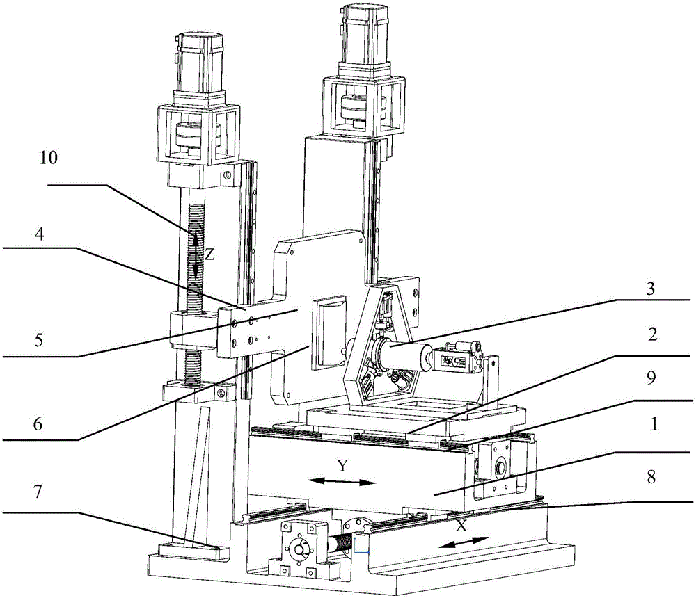
[0074] The X-axis guide rail 8 is fixedly installed on the bed 7, the Y-axis guide rail is installed on the X-axis guide rail upper slide plate 1, the Y-axis guide rail upper slide plate 2 is slidingly connected with the Y-axis guide rail 9, and the micro-movement polishing tool system 3 is installed on the Y-axis guide rail. On the slide plate 2 on the axis guide rail, the Z-axis guide rail 10 is fixedly installed on the bed 7, the Z-axis guide rail slide plate 4 is slidingly connected with the Z-axis guide rail, and the workpiece fixture 5 is fixed on the Z-axis guide rail slide plate 4;

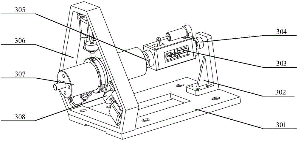
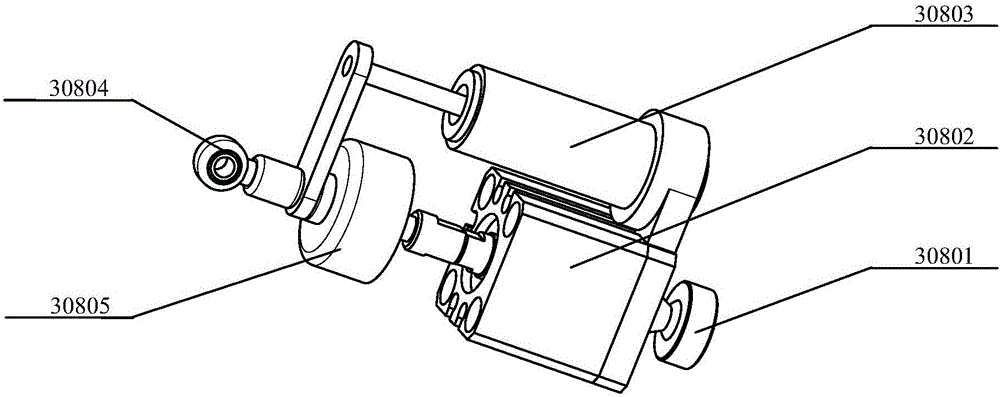
[0075] The fretting polishing tool system 3 is composed of a connecting plate 301, a spindle base 302, an axial force-position coupling unit 303, a cage coupling 304, a ball spline 305, a fixed bracket 306, an electric spindle 307, and three sets of radial The force-position coupling unit 308 is composed of the fixed bracket 306 and the connecting plate 301. The three sets of force-position...


PUM


Abstract

The invention relates to a force position coupling micro-motion precise polishing device and an online force detection and control method, and belongs to the field of machine manufacturing. An X-axis guide rail is fixedly installed on a machine body, and a Y-axis guide rail is installed on a slide carriage of the X-axis guide rail. A slide carriage of the Y-axis guide rail is slidably connected with the Y-axis guide rail. A micro-motion polishing tool system is installed on the slide carriage of the Y-axis guide rail. A Z-axis guide rail is fixedly installed on the machine body. A slide carriage of the Z-axis guide rail is slidably connected with the Z-axis guide rail. A workpiece clamp is fixed to the slide carriage of the Z-axis guide rail. According to the force position coupling micro-motion precise polishing device and the online force detection and control method, three-dimensional movement is provided by a machine, axial and radial micro-motion adjustment of the micro-motion polishing tool system can be achieved, and therefore machining of surfaces of complex workpieces can be achieved; the initial position of a spindle keeps unchanged in the machining process, and the magnitude of contact force of a cutter and the workpieces can be detected online, so that research of the relation of the contact force and the machining quality of the workpieces is facilitated; and meanwhile, control over the contact force of the cutter and the workpieces in the polishing process can be achieved through the micro-motion polishing tool system, and the purpose of improving the machining precision can be well achieved.

Description

technical field [0001] The invention belongs to the field of mechanical manufacturing, in particular to an online force detection and control method for force-position coupling micro-motion precision polishing. Background technique [0002] Precision machining and ultra-precision machining technology is an important basic guarantee for the development of cutting-edge national defense technology, and is an important technology of strategic significance. However, the precision polishing platform will inevitably have problems such as deformation and unstable mechanical movement. Common polishing machine spindles are rigidly connected to the tool, which is not only difficult to adapt to changes in free-form surfaces, but also difficult to control the surface roughness. During machining, it is usually impossible to obtain the dynamic change of the contact force between the tool and the workpiece during the machining process, and corresponding feedback adjustment cannot be perfor...

Claims


Application Information

Patent Timeline
IPC IPC(8): B24B49/16B24B41/02G05B13/04
CPCB24B41/02B24B49/165G05B13/042
Inventor 冀世军张祚华赵继张富刘义军翟春阳
Owner JILIN UNIV
Why Eureka
Try Eureka