
Self-cleaning fish tank

An automatic cleaning and fish tank technology, applied in fish farming, application, climate change adaptation, etc., can solve the problems of difficult cleaning, inability to be discharged, troublesome, etc., to save cleaning time and facilitate cleaning.

Active Publication Date: 2016-05-04
海门市创豪工业设计有限公司
View PDF9 Cites 7 Cited by
  • Summary
  • Abstract
  • Description
  • Claims
  • Application Information

AI Technical Summary

Problems solved by technology

[0002] Many households have ornamental fish, and ornamental fish are kept in fish tanks for breeding. In order to ensure the continued health of ornamental fish, it is usually necessary to replace the water in the fish tank after a period of breeding. The current common method is to open a water outlet at the bottom of the fish tank , the opening and closing of the water outlet is controlled by a switch, but in actual operation, the water is directly discharged from the water outlet quickly, and the dirt deposited on the bottom of the fish tank, such as dirt that cannot be sucked up and filtered by the filtration system because it is far away from the filtration system, It cannot be discharged, especially the stolen goods far away from the water outlet are difficult to discharge from the water outlet, and often need to be cleaned with the help of external tools, which is not only troublesome but also difficult to clean

Method used


Image

  • Self-cleaning fish tank
  • Self-cleaning fish tank

Examples


Embodiment Construction

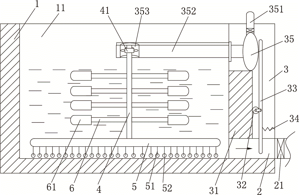
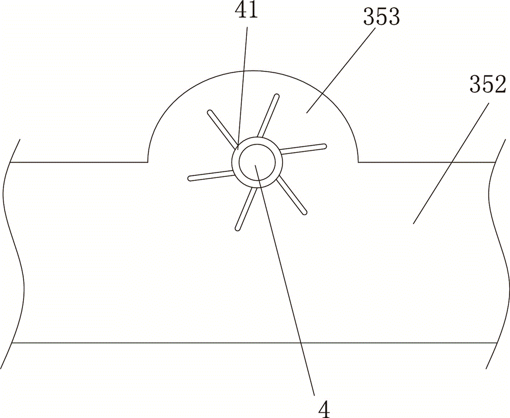
[0010] The present invention will be described in further detail below in conjunction with accompanying drawing and specific embodiment: see figure 1 and figure 2 , an automatic cleaning fish tank, including a fish tank body 1, a cavity 11 for raising fish is provided in the fish tank body 1, an outlet pipe 2 is connected to the right side of the fish tank body 1, and the outlet pipe 2 is connected to the The cavities 11 communicate with each other, the water outlet pipe 2 is provided with a water outlet switch 21, and a cavity is provided in the right side wall of the fish tank body 1 to form a cavity part 3, and the cavity part 3 and the water outlet pipe 2 are connected to each other. Connected, the inner wall of the cavity part 3 is provided with a support block 31, the right side wall of the support block 31 is provided with a ball 32, the ball 32 is rotatably connected with a push piece 33, the lower end of the push piece 33 The end part extends into the water outlet p...


PUM


Abstract

The invention discloses a self-cleaning fish tank which comprises a fish tank body. A cavity is formed in the fish tank body. A water outlet pipe is arranged on the fish tank body. A cavity is formed in the right side wall of the fish tank body and forms a cavity part. A supporting block is arranged on the inner wall of the cavity part. A ball is arranged on the right side wall of the supporting block and connected with a push piece in a rotating mode. The lower end of the push piece extends into the water outlet pipe. A spring is arranged between the right side of the push piece and the inner wall of the cavity part. A gas bag is arranged on the upper side face of the supporting block. The gas bag and the push piece abut against each other. The upper end of the gas bag is connected with a gas inlet pipe. The left side of the gas bag is connected with a gas outlet pipe. A semicircular groove is formed in the gas outlet pipe. A rotating shaft is arranged on the inner wall of the gas outlet pipe and connected with fan blades. The lower end of the rotating shaft is fixedly connected with a circular connection plate. Bristles are arranged on the lower side face of the circular connection plate. Stop rods are arranged in the circumferential direction of the rotating shaft and provided with connection pieces. During water changing, the bottom face inside the fish tank is automatically swept.

Description

technical field [0001] The invention relates to an automatic cleaning fish tank. Background technique [0002] Many households have ornamental fish, and ornamental fish are kept in fish tanks for breeding. In order to ensure the continued health of ornamental fish, it is usually necessary to replace the water in the fish tank after a period of breeding. The current common method is to open a water outlet at the bottom of the fish tank , the opening and closing of the water outlet is controlled by a switch, but in actual operation, the water is directly discharged from the water outlet quickly, and the dirt deposited on the bottom of the fish tank, such as dirt that cannot be sucked up and filtered by the filtration system because it is far away from the filtration system, The stolen goods that cannot be discharged, especially those far away from the water outlet, are difficult to discharge from the water outlet, and often need to be cleaned with the help of external tools, w...

Claims


Application Information

Patent Timeline
Patent Type & Authority Applications(China)
IPC IPC(8): A01K61/00
CPCY02A40/81
Inventor 余威倪莉莉
Owner 海门市创豪工业设计有限公司
Learn More