Visual microscope
A microscope and objective lens technology, applied in the field of medical equipment, can solve problems such as inconvenient operation, complex structure, general imaging effect, etc., and achieve the effects of convenient adjustment of focal length, clear imaging, and good display effect
- Summary
- Abstract
- Description
- Claims
- Application Information
AI Technical Summary
Problems solved by technology
Method used
Image
Examples
Embodiment 1
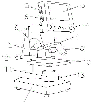
[0024] refer to figure 1 As shown, a visual microscope includes a base 1, a main frame 2, a display screen 3 and an objective lens turntable 4, the support 2 is arranged on the base 1, the support 2 is connected with the base 1, the display screen 3 and the The objective lens turntable 4 is arranged on the main frame 2. When in use, the slide glass is placed on the stage 10, and the image information can be displayed on the display screen by rotating the objective lens turntable 4 to adjust the 8 magnifications of the appropriate objective lens. SD card slot 5 and USB interface 6 can transmit and save data, described display screen 3 side is provided with SD card slot 5 and USB interface 6, described display screen 3 below is provided with control button 7, and described objective lens turntable 4 An objective lens 8 is arranged below, and the objective lens 8 is connected to the objective lens turret 4 in rotation, and an illumination dome light 9 is arranged on one side of t...
Embodiment 2
[0039] refer to figure 1As shown, a visual microscope includes a base 1, a main frame 2, a display screen 3 and an objective lens turntable 4, the support 2 is arranged on the base 1, the support 2 is connected with the base 1, the display screen 3 and the The objective lens turntable 4 is arranged on the main frame 2. When in use, the slide glass is placed on the stage 10, and the image information can be displayed on the display screen by rotating the objective lens turntable 4 to adjust the 8 magnifications of the appropriate objective lens. SD card slot 5 and USB interface 6 can transmit and save data, described display screen 3 side is provided with SD card slot 5 and USB interface 6, described display screen 3 below is provided with control button 7, and described objective lens turntable 4 An objective lens 8 is arranged below, and the objective lens 8 is connected to the objective lens turret 4 in rotation, and an illumination dome light 9 is arranged on one side of th...
Embodiment 3
[0054] refer to figure 1 As shown, a visual microscope includes a base 1, a main frame 2, a display screen 3 and an objective lens turntable 4, the support 2 is arranged on the base 1, the support 2 is connected with the base 1, the display screen 3 and the The objective lens turntable 4 is arranged on the main frame 2. When in use, the slide glass is placed on the stage 10, and the image information can be displayed on the display screen by rotating the objective lens turntable 4 to adjust the 8 magnifications of the appropriate objective lens. SD card slot 5 and USB interface 6 can transmit and save data, described display screen 3 side is provided with SD card slot 5 and USB interface 6, described display screen 3 below is provided with control button 7, and described objective lens turntable 4 An objective lens 8 is arranged below, and the objective lens 8 is connected to the objective lens turret 4 in rotation, and an illumination dome light 9 is arranged on one side of t...
PUM
 Abstract
Description
Claims
Application Information
 - R&D
- Intellectual Property
- Life Sciences
- Materials
- Tech Scout
- Unparalleled Data Quality
- Higher Quality Content
- 60% Fewer Hallucinations
Browse by: Latest US Patents, China's latest patents, Technical Efficacy Thesaurus, Application Domain, Technology Topic, Popular Technical Reports.
© 2025 PatSnap. All rights reserved.Legal|Privacy policy|Modern Slavery Act Transparency Statement|Sitemap|About US| Contact US: help@patsnap.com

