Target object dynamic tracking and measurement positioning method

A target object and dynamic tracking technology, applied in image data processing, television, instruments, etc., can solve the problems of lack of intelligence, inability to provide target object position information, inaccurate target object tracking and positioning, etc., to improve the level of intelligence Effect

Inactive Publication Date: 2016-05-04
LANZHOU UNIVERSITY OF TECHNOLOGY
View PDF3 Cites 45 Cited by
  • Summary
  • Abstract
  • Description
  • Claims
  • Application Information

AI Technical Summary

Problems solved by technology

[0002] At present, the application of video surveillance is becoming more and more common, which has brought immeasurable effects to people's work in the field of security. However, the existing surveillance technology is low in intelligence and still relies on a large number of human resources to identify video content to deal with dangers. and emergencies
Most traditional video surveillance systems can only collect video information in the monitoring area. This monitoring method relies on manual continuous work to detect sudden and dangerous situations in the monitoring area, and lacks intelligent early warning of dangerous information in the monitoring area. The actual operation requires investment A large amount of manpower is used for real-time or post-event analysis, and the images returned by this video surveillance method cannot provide accurate location information of the target object. Operators can only guess the approximate location of the target object based on experience, making the tracking and positioning of the target object inaccurate and lacking intelligence

Method used


Image

  • Target object dynamic tracking and measurement positioning method
  • Target object dynamic tracking and measurement positioning method
  • Target object dynamic tracking and measurement positioning method

Examples


Embodiment Construction

[0020] The present invention will be described in further detail below in conjunction with the accompanying drawings.

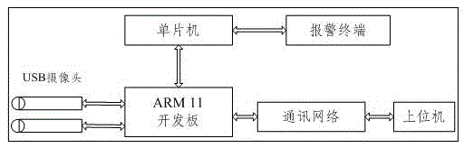
[0021] The general principle of the present invention is shown as figure 1 As shown, the binocular image information is collected through the left and right cameras of the USB interface, and the image is processed by the ARM11 development board to capture the position and geometric size information of the target object, which provides the basis for automatic early warning and corresponding measures for the background staff.

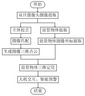
[0022] In the present invention, the target object measurement and positioning process is as follows: figure 2 As shown, the binocular image information is collected through the left and right cameras, with 16 12 The checkerboard is the calibration object, and the camera is calibrated stereoscopically using the principle of minimizing the distance and maximizing the projection, obtaining the camera parameters and correcting the distor...


PUM


Abstract

The invention discloses a target object dynamic tracking and measurement positioning method. According to the method, two cameras are used for collecting images of a monitoring region; the backgrounds of the monitoring region are dynamically updated; a target object is extracted; a three-dimensional point cloud of a viewing angle region is generated by using a binocular identification positioning principle; the target object is dynamically tracked and positioned through combining the target object extraction and the binocular identification positioning principle. According to the method of the invention, vision distance measurement and target tracking are combined in the video monitoring field; the pixel coordinate of the image in which the target is located is determined; the target object is locked through combining the three-dimensional point cloud generated by the vision distance measurement; the three-dimensional coordinate of the target object is determined. When the target object enters a warning region, the system warns; therefore real time early warning is realized; the captured position information of the target object provides scientific basis for actual operation of a backstage worker.

Description

technical field [0001] The invention relates to the technical field of video security and human-computer interaction, in particular to a method for dynamic tracking, measurement and positioning of a target object in the field of video surveillance. Background technique [0002] At present, the application of video surveillance is becoming more and more common, which has brought immeasurable effects to people's work in the field of security. However, the existing surveillance technology is low in intelligence and still relies on a large number of human resources to identify video content to deal with dangers. and emergencies. Most traditional video surveillance systems can only collect video information in the monitoring area. This monitoring method relies on manual continuous work to detect sudden and dangerous situations in the monitoring area, and lacks intelligent early warning of dangerous information in the monitoring area. The actual operation requires investment A la...

Claims


Application Information

Patent Timeline
Patent Type & Authority Applications(China)
IPC IPC(8): G06K9/00H04N7/18
CPCH04N7/181G06T2207/30232G06T2207/10021G06V20/46G06V10/247G06V10/443
Inventor 赵宏郭哲包广斌刘诗钊张乐侯春宁曹昶韩泽宇
Owner LANZHOU UNIVERSITY OF TECHNOLOGY
Why Eureka
Try Eureka