
Array substrate, driving method thereof and display panel

A technology of an array substrate and a driving method, which is applied to static indicators, instruments, etc., can solve the problems of increasing the equivalent resistance of the test circuit, increasing the time required for charging the data line, and failing to meet the charging speed of the data line, so as to avoid Effect of material consumption and load reduction

Active Publication Date: 2016-05-04
WUHAN TIANMA MICRO ELECTRONICS CO LTD +1
View PDF5 Cites 15 Cited by
  • Summary
  • Abstract
  • Description
  • Claims
  • Application Information

AI Technical Summary

Problems solved by technology

For a non-striped sub-pixel array, if you want to display a pure color picture such as red, green, blue, etc., you need to apply a signal with a higher frequency of level signal change to each data line, and because the data provided to the sub-pixel The frequency of level signal changes on the signal line of the signal is high, which makes the load of the test circuit too large, increases the equivalent resistance in the test circuit, and thus increases the time required for charging the data line, which cannot meet the normal display of solid-color images. The charging speed of the data line, the signal of some data lines will be delayed, causing the problem of uneven display, which cannot normally reflect the display performance of the array substrate
In this sub-pixel arrangement, the color shift of the solid-color picture can only be detected in the electrical test stage, which may cause the consumption of materials such as driving circuits, flexible circuit boards, and polarizers.

Method used


Image

  • Array substrate, driving method thereof and display panel
  • Array substrate, driving method thereof and display panel
  • Array substrate, driving method thereof and display panel

Examples


Embodiment Construction

[0020] The application will be further described in detail below in conjunction with the accompanying drawings and embodiments. It should be understood that the specific embodiments described here are only used to explain related inventions, rather than to limit the invention. It should also be noted that, for the convenience of description, only the parts related to the related invention are shown in the drawings.

[0021] It should be noted that, in the case of no conflict, the embodiments in the present application and the features in the embodiments can be combined with each other. The present application will be described in detail below with reference to the accompanying drawings and embodiments.

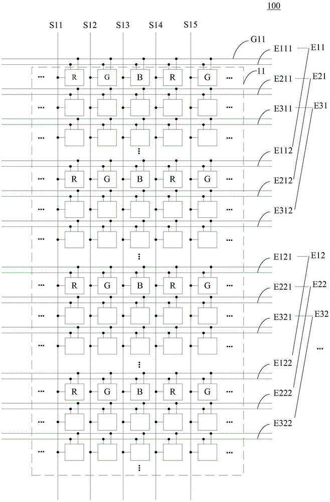
[0022] Please refer to figure 1 , which shows a schematic structural view of an array substrate to which the driving method of the present application can be applied. Such as figure 1 As shown, the array substrate 100 includes sub-pixels 11 arranged in an array and a plura...


PUM


Abstract

The invention discloses an array substrate, a driving method thereof and a display panel. The array substrate at least comprises sub pixels distributed in an array mode, a plurality of first light-emitting control signal wire groups and a plurality of second light-emitting control signal wire groups, each first light-emitting control signal wire group comprises at least one first light-emitting control signal wire, and each second light-emitting control signal wire group comprises at least one second light-emitting control signal wire; in the sub pixels in each line, the colors of the sub pixels connected with the first light-emitting control signal wires are the same. The driving method includes the steps that first signals are applied to the first light-emitting control signal wire groups one group by one group, and meanwhile second signals are applied to the other light-emitting control signal wire groups so that the sub pixels connected with the first light-emitting control signal wire groups can be displayed, and the sub pixels connected with the other light-emitting control signal wire groups can not be displayer. By means of the driving method, testing of the display performance of the array substrate in the vision testing phase can be achieved.

Description

technical field [0001] The present application relates to the field of display technology, in particular to the field of driving technology of a display panel, in particular to an array substrate, a driving method thereof, and a display panel. Background technique [0002] In the design of the display panel, the sub-pixel arrays on the array substrate may have various arrangements. Such as striped arrangement and non-striped arrangement. In the striped arrangement, the same column of sub-pixels in the direction of the data line has the same color, and the sub-pixels are arranged repeatedly in the order of red sub-pixels, green sub-pixels, and blue sub-pixels in the direction of the scanning line; In the arrangement mode, the colors of the same column of sub-pixels in the direction of the data lines may be different, and each data line drives sub-pixels of multiple colors. [0003] Usually, when manufacturing a display panel, materials such as an array substrate, a driver I...

Claims


Application Information

Patent Timeline
IPC IPC(8): G09G3/32
CPCG09G3/3258
Inventor 朱敏逾钱栋
Owner WUHAN TIANMA MICRO ELECTRONICS CO LTD
Learn More