Energy switch for on-axis electrical coupling standing wave accelerating tube

An energy switch and accelerating tube technology, applied in linear accelerators, electrical components, accelerators, etc., can solve the problem that energy switch technology is still blank, and achieve the effect of multi-level adjustable energy

Active Publication Date: 2016-05-04
UNIV OF SCI & TECH OF CHINA
View PDF10 Cites 12 Cited by
  • Summary
  • Abstract
  • Description
  • Claims
  • Application Information

AI Technical Summary

Problems solved by technology

For the on-axis electrically coupled standing wave accelerator tube with the simplest pro...

Method used


Image

  • Energy switch for on-axis electrical coupling standing wave accelerating tube
  • Energy switch for on-axis electrical coupling standing wave accelerating tube
  • Energy switch for on-axis electrical coupling standing wave accelerating tube

Examples


specific Embodiment

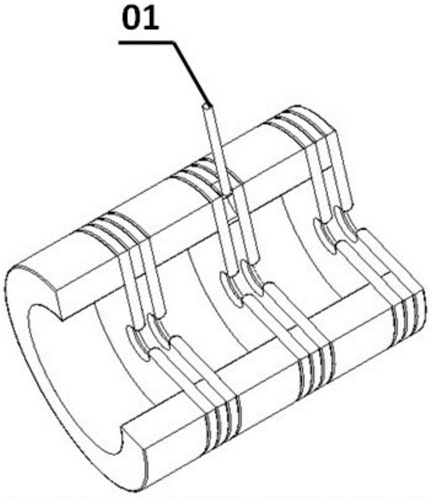
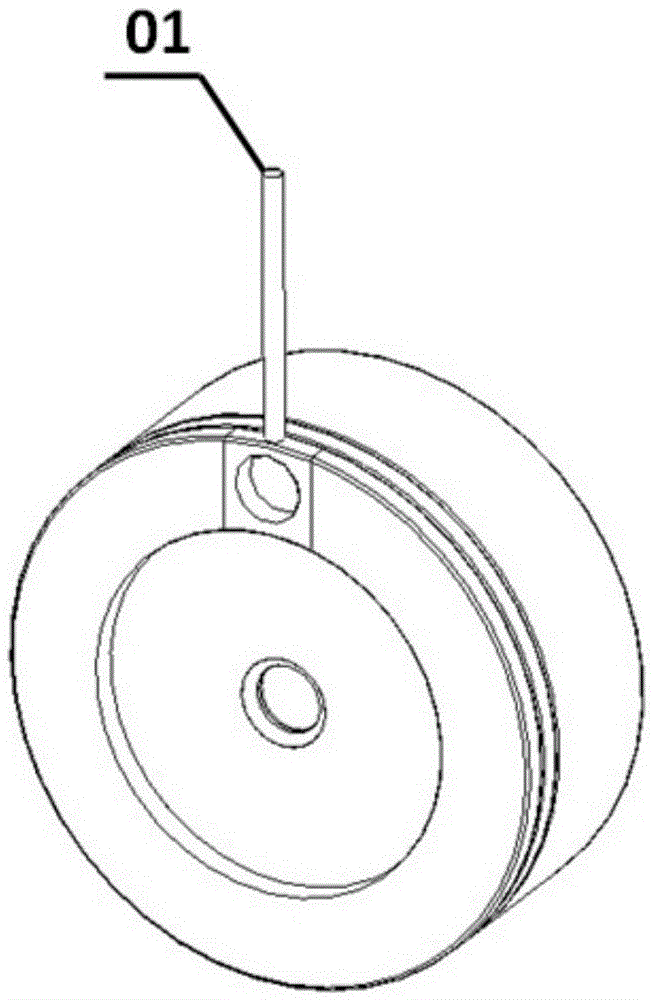
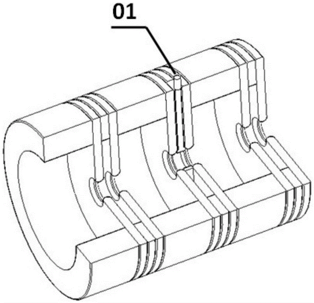
[0027] The on-axis electrically coupled standing wave accelerating tube is composed of large cavity (accelerating cavity) and small cavity (coupling cavity) alternately, and its partial structure is as follows: figure 1 shown. When the microwave power is fed into the accelerating tube, the electrons are accelerated by the microwave electric field established in the accelerating cavity; while the coupling cavity only couples the transmission of the microwave power between the accelerating cavities, and does not contribute to the energy of the electrons. By controlling the structure of the coupled cavity at a specific position, the microwave power transmitted to the back-end accelerating cavity can be changed, thereby controlling the energy of the electrons, that is, the energy switch function. The energy switch 01 can be controlled by the mechanical structure to pull out or enter the coupling cavity.

[0028] figure 1 The mechanical structure diagram of the accelerating tube ...


PUM


Abstract

The invention discloses an energy switch for an on-axis electrical coupling standing wave accelerating tube. The on-axis electrical coupling standing wave accelerating tube comprises multiple accelerating cavities and coupling cavities arranged alternatively, wherein apertures are arranged among the accelerating cavities and the coupling cavities; circular holes are formed in the middle parts of the apertures; the energy switch comprises a platy front end and a pull rod at the back end; a circular hole is formed in the middle of the platy front end; the platy front end is inserted into the coupling cavities, and the pull rod stretches out of the side walls of the coupling cavities; and when the platy front end is inserted in a position where the circular hole in the platy front end coincides with the circular holes in the apertures, a circular waveguide structure is formed by the three circular holes. The energy multi-gear adjustability of a medical electron linear accelerator can be realized through insertion and pull-out of the energy switch.

Description

technical field [0001] The invention relates to a medical electron linear accelerator, in particular to an energy switch electrically coupled to a standing wave accelerating tube on an axis. Background technique [0002] Medical electron linear accelerators are one of the main therapeutic modalities in cancer treatment. The electron beam emitted by the medical electron linear accelerator bombards the target to generate X-rays, and the X-rays are irradiated to kill tumor cells to achieve the purpose of treating cancer. Depending on the location of the lesion, X-rays with different energies are required for irradiation. Therefore, the medical electron linear accelerator is required to have the performance of multi-level adjustable energy (energy switch). [0003] There are two types of medical electron linear accelerators: traveling wave accelerators and standing wave accelerators. Among them, the standing wave accelerator has a large shunt impedance and high acceleration ef...

Claims


Application Information

Patent Timeline
IPC IPC(8): H05H9/04H05H7/12
CPCH05H7/12H05H9/044H05H2007/125
Inventor 金凯何志刚裴香涛王琳黄贵荣
Owner UNIV OF SCI & TECH OF CHINA
Why Eureka
Try Eureka