Massage system for a vehicle seat

A vehicle seat and a series of technologies are applied in the direction of vehicle seats, special positions of vehicles, and vehicle components, etc., which can solve problems such as the complexity of the massage system, and achieve the effects of simplifying the overall space requirements, simplifying the pipeline layout, and simplifying the installation

Active Publication Date: 2016-05-04
LEAR CORP
View PDF6 Cites 6 Cited by
  • Summary
  • Abstract
  • Description
  • Claims
  • Application Information

AI Technical Summary

Problems solved by technology

[0004] This massage system for vehicle seats is very complex due to the very large number of controllable valves, i.e. 2n+2 valves for a series of n air cells

Method used


Image

  • Massage system for a vehicle seat
  • Massage system for a vehicle seat
  • Massage system for a vehicle seat

Examples


Embodiment Construction

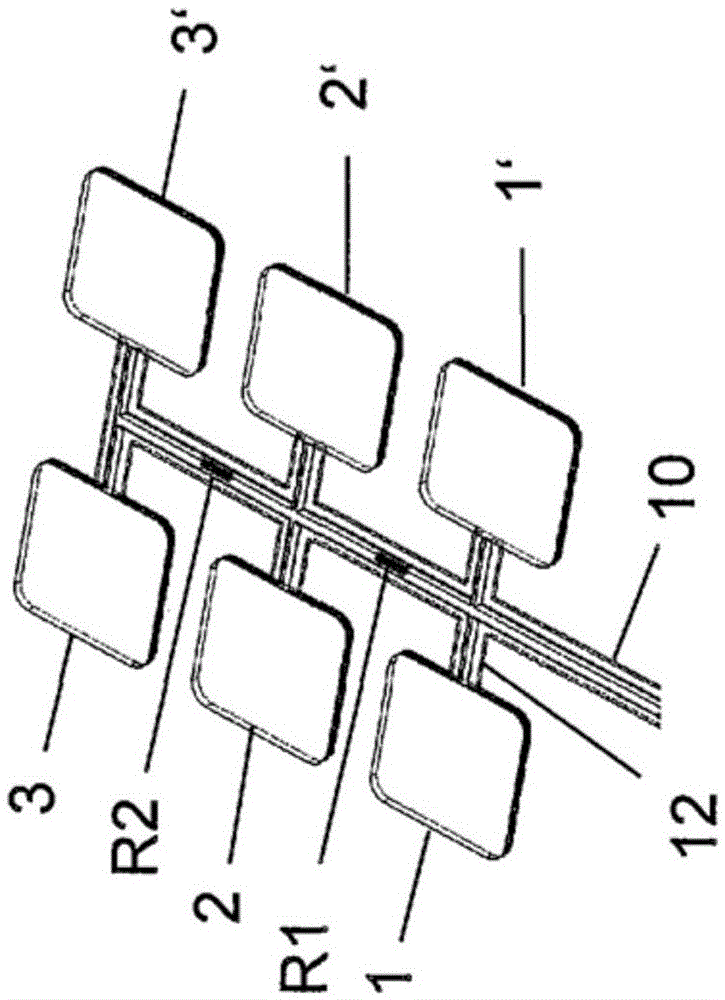
[0037] in Figure 1a Here, a schematic perspective view of a massage system is shown, which has a first series of three air units 1, 2 and 3, which are connected to a common supply line 10 via a connection line 12. In a symmetrical manner, the second series of air units 1', 2'and 3'are connected to the common supply line 10. A pump (not shown) is used to supply compressed air to the supply line 10.

[0038] Between each pair of successive air units 1, 2 and 2, 3, flow restrictors R1 and R2 are respectively arranged. The same applies to the second series of air units 1', 2'and 3'.

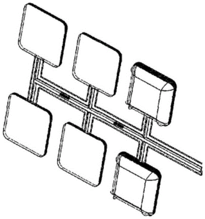
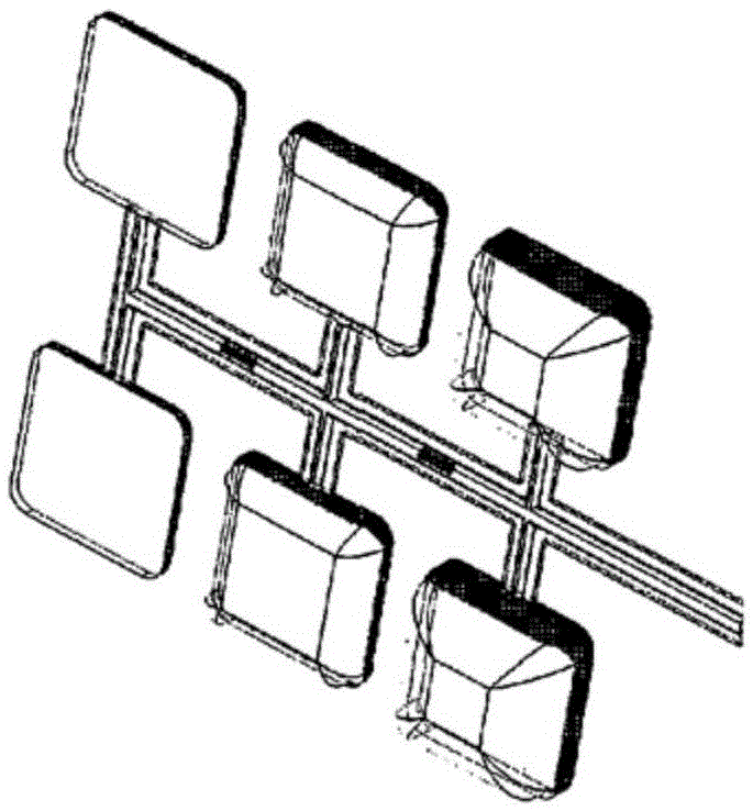
[0039] In the initial state 1a, the pump has not been activated yet, and all air units 1, 2, 3, 1', 2', 3'are completely deflated. in Figure 1b , The pump has started to supply compressed air, and the first air unit 1, 1'of the two parallel series of air units has begun to be inflated. Due to the restrictor, the inflation of the air unit starts in the first air unit 1 (and 1'in the second series of a...


PUM


Abstract

The present invention provides a massage system for a vehicle seat comprising a plurality of inflatable air cells arranged in a series of subsequent air cells (1, 2, 3), a supply line structure (10, 12; 10a, 12a) from and to each of the plurality of air cells, a pump (14) for supplying air under pressure to the supply line structure, a control or switch unit for controlling the operation of the pump, venting means for venting the supply line structure, means for controlling air flow to and from the air cells to provide a sequential inflation / deflation along said series of air cells, characterized in that said means for controlling air flow are provided by a plurality of flow restrictors (R1, R2, R3) having reduced flow cross-sections, said flow restrictors are arranged in such a manner that between each pair of subsequent air cells (1, 2, 3) in said series of air cells (1, 2, 3) a flow restrictor is disposed in the supply line structure such that the flow resistance from the pump and the venting means to any air cell in said series of air cells (1, 2, 3) is increasing along said series of air cells such that the air cells are inflated in sequence along said series of air cells upon the pump supplying air under pressure to the supply line structure, wherein the flow restrictors are dimensioned such that the delay time between a cell reaching 80% of its volume fill capacity to the next subsequent cell in the series of air cells reaching 80% of its volume fill capacity is between 0,5 s to 30 s, and are deflated in sequence along said series of air cells when venting said supply line structure by said venting means.

Description

Technical field [0001] The present invention relates to a massage system for a vehicle seat, which includes a plurality of inflatable air units arranged in a successive series of air units, and has an air unit for fluid communication with each of the series of air units The connected supply line structure, the pump for supplying air to the supply line structure under pressure, the control unit or switching unit for controlling the operation of the pump, the exhaust device for exhausting the supply line structure, the Control the flow of air into and out of the air unit to provide a device to inflate / deflate sequentially along the series of air units. Background technique [0002] Drivers and passengers of motor vehicles, especially when traveling for long distances, often experience discomfort, which is caused by prolonged static posture when sitting in the vehicle seat. This not only feels uncomfortable and causes back pain, for example, but also causes permanent damage to heal...

Claims


Application Information

Patent Timeline
Patent Type & Authority Applications(China)
IPC IPC(8): B60N2/44A61H9/00B60N2/90
CPCA61H9/0078A61H2201/0149A61H2201/1623A61H2201/5002A61H2205/081B60N2/976
Inventor 彼得·奥伯格扎里·萨恩丹尼尔·约瑟夫森
Owner LEAR CORP
Why Eureka
Try Eureka