Disassembly-free and hole-free mold width adjustment device for sheet turning and forming machine

A forming machine and thin plate car technology, applied in forming tools, metal processing equipment, manufacturing tools, etc., can solve the problems of high time-consuming, waste, traces left on the base material plate, etc., to reduce the width of the mold and reduce the time for mold change , Eliminate the effect of base metal damage

Inactive Publication Date: 2016-05-11
覃艺诗
0 Cites 2 Cited by

AI-Extracted Technical Summary

Problems solved by technology

[0002] The thin plate forming machine is a multi-purpose machine in the construction and machinery industries. Due to the different shapes and widths of the processed products, it is necessary to disassemble all dozens of roller wheels every time the product specification is changed, an...

Abstract

A disassembly-free and hole-free mold width adjustment device for a sheet turning and forming machine comprises a main shaft, two pressing rollers and a widened wheel, the main shaft is erected on a bearing base, the two pressing rollers are arranged on the main shaft in a sleeving mode, and inner step holes are formed in the opposite surfaces of the two pressing rollers; the widened wheel is formed by combining two half-round wheels, outer steps matched with the inner step holes are arranged on the two planes of the widened wheel, and the widened wheel is arranged on the main shaft in a clamping and sleeving mode and is located between the two pressing rollers; the pressing rollers and the widened wheel are fixed to the main shaft in a pressed mode through fastening assemblies. In the use process, the fastening assemblies are screwed and fastened, and the pressing rollers and the widened wheel are pressed tightly; when the product specification needs to be replaced, users just need to unscrew the fastening assemblies, increase or reduce the widened wheel appropriately and screw the fastening assemblies, the mold change time can be greatly shortened, the labor intensity can be lowered, mold adjustment can be realized without the main shaft, the mold width can be fast increased or reduced without any bolts or auxiliary clamping devices, damage to base metal can be eliminated, and the product quality can be improved.

Application Domain

Technology Topic

EngineeringBase metal +2

Image

  • Disassembly-free and hole-free mold width adjustment device for sheet turning and forming machine
  • Disassembly-free and hole-free mold width adjustment device for sheet turning and forming machine
  • Disassembly-free and hole-free mold width adjustment device for sheet turning and forming machine

Examples

  • Experimental program(1)

Example Embodiment

[0014] The technical solutions in the embodiments of the present invention will be clearly and completely described below in conjunction with the accompanying drawings in the embodiments of the present invention. Obviously, the described embodiments are only a part of the embodiments of the present invention, rather than all the embodiments. Based on the embodiments of the present invention, all other embodiments obtained by those of ordinary skill in the art without creative work shall fall within the protection scope of the present invention.
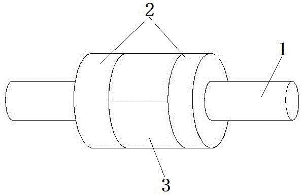
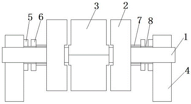
[0015] See Figure 1-3 In the embodiment of the present invention, a non-unloading and non-porous mold width adjustment device of a sheet car forming machine includes a main shaft 1, a pressure roller 2, and a widening wheel 3. The main shaft 1 is erected on a bearing seat 4, and the pressure roller 2 There are two, which are sleeved on the main shaft 1, and the opposite surfaces of the two pressure rollers 2 are respectively provided with inner step holes 9; the widening wheel 3 is composed of two semicircular wheels, and the widening wheel 3 has two flat surfaces. An outer step 10 matching the inner step hole 9 is provided, and the widening wheel 3 is clamped on the main shaft 1 and located between the two pressing rollers 2.
[0016] The pressure roller 2 and the widening wheel 3 are compressed and fixed on the main shaft 1 by a fastening component. The fastening component includes a positioning nut 5, an adjusting nut 6 and a bushing 7. The positioning nut 5 and the adjusting nut 6 are screwed on On the main shaft 1, the positioning nut 5 is close to the bearing seat 4, and the main shaft 1 between the adjusting nut 6 and the pressure roller 2 is also sleeved with a bushing 7.
[0017] Tighten the adjusting nut 6 when in use, and press the roller 2 and the widening wheel 3 together; when the product specifications need to be changed, just unscrew the adjusting nut 6, increase or decrease the widening wheel 3 appropriately, and then turn it again Just tighten the adjusting nut 6.
[0018] The invention can reduce the time of mold changing, reduce labor intensity, adjust the mold without the main shaft, and without any bolts or auxiliary clamping devices, realize rapid increase (reduce) of mold width, eliminate damage to the base material, and improve product quality.
[0019] For those skilled in the art, it is obvious that the present invention is not limited to the details of the foregoing exemplary embodiments, and the present invention can be implemented in other specific forms without departing from the spirit or basic characteristics of the present invention. Therefore, from any point of view, the embodiments should be regarded as exemplary and non-limiting. The scope of the present invention is defined by the appended claims rather than the foregoing description, and therefore it is intended to fall within the claims. All changes within the meaning and scope of equivalent elements of are included in the present invention. Any reference signs in the claims should not be regarded as limiting the claims involved.
[0020] In addition, it should be understood that although this specification is described in accordance with the implementation manners, not each implementation manner only includes an independent technical solution. This narration in the specification is only for clarity, and those skilled in the art should consider the specification as a whole The technical solutions in the embodiments can also be appropriately combined to form other implementations that can be understood by those skilled in the art.

PUM

no PUM

Description & Claims & Application Information

We can also present the details of the Description, Claims and Application information to help users get a comprehensive understanding of the technical details of the patent, such as background art, summary of invention, brief description of drawings, description of embodiments, and other original content. On the other hand, users can also determine the specific scope of protection of the technology through the list of claims; as well as understand the changes in the life cycle of the technology with the presentation of the patent timeline. Login to view more.

Similar technology patents

Method and device for controlling mould exchanging time

InactiveCN102004948AReduce die change timeMeet service level requirementsInstrumentsTime controlLevel of service
Owner:YONYOU

Fast positioning device of automobile glass tempered air grid

InactiveCN101717186AEnsure that the hole position corresponds to the dimensional accuracyReduce die change timeGlass tempering apparatusElectrical and Electronics engineering
Owner:FUYAO GRP SHANGHAI AUTOMOBILE GLASS CO LTD

Extrusion granulator capable of rapidly changing die

PendingCN114225830AReduce die change timeImprove continuitySievingScreeningElectric machineryClutch
Owner:GUANGXI LIYUANBAO SCI & TECH

Classification and recommendation of technical efficacy words

  • Reduce labor intensity
  • Reduce die change time

City regional railway signal system and control method thereof

ActiveCN103754242ARun fastReduce labor intensityAutomatic systemsRailway signalEngineering
Owner:CHINA RAILWAY SIYUAN SURVEY & DESIGN GRP

Lifting type die changing trolley and die changing method thereof

ActiveCN106475473ASmooth mold change processReduce die change timeShaping toolsMetal working apparatusElectrical controlEngineering
Owner:JIANGSU ZHISHI TECH CO LTD

Quick hoisting type mold changing trolley and mold changing method thereof

ActiveCN106391881ASmooth mold change processReduce die change timeShaping toolsBearing surfaceElectrical control
Owner:JIANGSU ZHISHI TECH CO LTD

Quick installation method of riveting-pressing die

InactiveCN104772397AEasy to install and replace moldsReduce die change timeShaping toolsTool steelMagnet
Owner:上海惠亚电子有限公司

Quick change device for female die

InactiveCN103008457AReduce die change timeOvercoming installation gapsShaping toolsCushionEngineering
Owner:FUJIAN UNIV OF TECH
Why Eureka
Try Eureka