Coil inserting die for coil inserting machine

A technology of wire embedding mold and wire embedding machine, which is applied in the direction of electromechanical devices, manufacturing motor generators, electrical components, etc., can solve the problems of no modularization, a lot of time, and inconvenient replacement, so as to improve the use efficiency and save mold replacement time, convenient effect of replacement

Inactive Publication Date: 2015-03-25
NIDE MECHANICAL EQUIP
View PDF8 Cites 3 Cited by
  • Summary
  • Abstract
  • Description
  • Claims
  • Application Information

AI Technical Summary

Problems solved by technology

[0002] The wire embedding machine is used in the motor industry to embed the winding wire of the motor into the motor stator. The mold structure for the wire embedding in the existing wire embedding machine is complex, and there is no modularization, so it is very inconvenient to replace, especially after replacing the new mould. It takes a lot of time to adjust, and it usually takes 1.5 hours to 2 hours to replace a set of molds, which will inevitably lead to low production efficiency of the embedding machine.

Method used


Image

  • Coil inserting die for coil inserting machine
  • Coil inserting die for coil inserting machine

Examples


Embodiment Construction

[0013] The present invention is described below in conjunction with accompanying drawing.

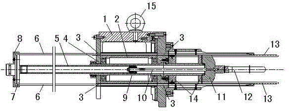
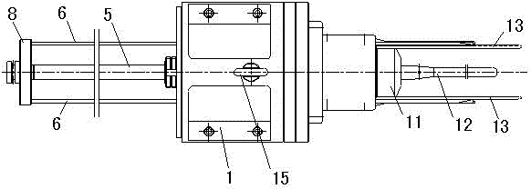
[0014] as attached figure 1 , 2 Shown is the wire embedding die for wire embedding machine according to the present invention, which includes a box body 1, a push rod sleeve 5, a pull rod 10, and a guide bar 13; the center of the box body 1 is provided with a mandrel 4; the core A material storehouse 2 is arranged rotatably around the shaft 4; the material storehouse 2 is arranged in the inner cavity of the box body 1; the mandrel 4 is hollow; one end of the push rod sleeve 5 is inserted into the mandrel 4, and connected to one end of the pull rod 10 through the push rod sleeve nut 9, the other end of the pull rod 10 is connected to the copper push head 11, and the outer end surface of the copper push head 11 is provided with a splitting needle 12, so The other end of the push rod sleeve 5 is provided with a push rod constellation 7; the push rod constellation 7 is horizontally provid...


PUM


Abstract

The invention discloses a coil inserting die for a coil inserting machine. The coil inserting die for the coil inserting machine comprises a tank, a push rod sleeve and a pull rod; a dabber is arranged in the center of the tank; a material warehouse is arranged on the dabber in the mode of being capable of rotating around the dabber; the material warehouse is arranged in an internal cavity of the tank; the dabber is hollow; one end of the push rod sleeve is inserted into the dabber and connected with one end of the pull rod through a push rod sleeve nut; the other end of the pull rod is connected with a copper push head; a coil distribution needle is arranged on the outer end face of the copper push head; the other end of the push rod sleeve is provided with a push rod base; multiple paper pushing rods are horizontally arranged along the external circumference of the push rod base; through holes corresponding to the paper push rods are formed in the tank with the dabber as the center, so that the paper push rods pass through the corresponding through holes and bring out and insert insulation paper in the material warehouse into a winding groove of a motor stator. By the adoption of the modular design, replacement is convenient, the die replacement time is shortened, and the use efficiency of equipment is improved.

Description

technical field [0001] The invention relates to an improvement of parts of a wire embedding machine, in particular to a wire embedding die for a wire embedding machine which is convenient to replace. Background technique [0002] The wire embedding machine is used in the motor industry to embed the winding wire of the motor into the motor stator. The mold structure for the wire embedding in the existing wire embedding machine is complex, and there is no modularization, so it is very inconvenient to replace, especially after replacing the new mould. It takes a lot of time to adjust, and it usually takes 1.5 hours to 2 hours to replace a set of molds, which will inevitably lead to low production efficiency of the embedding machine. For this reason, we have developed an easy-to-replace wire inserting die for the inserting machine. Contents of the invention [0003] In view of the above-mentioned existing technical problems, the object of the present invention is to propose a...

Claims


Application Information

Patent Timeline
Patent Type & Authority Applications(China)
IPC IPC(8): H02K15/085
Inventor 刘成章
Owner NIDE MECHANICAL EQUIP
Why Eureka
Try Eureka