Bridge vehicle top cover die

A top cover and mold technology, applied in the direction of forming tools, manufacturing tools, metal processing equipment, etc., to achieve the effects of reducing fatigue strength, improving tea production efficiency, and reducing waste

Active Publication Date: 2014-10-22
泰州英格伟精密机械有限公司
View PDF5 Cites 3 Cited by
  • Summary
  • Abstract
  • Description
  • Claims
  • Application Information

AI Technical Summary

Problems solved by technology

[0004] The invention provides an automobile axle roof mold which can meet the production needs of the roof with sunroof and the roof without sunroof at the same time, and is not easy to produce indentation, and solves the problems of roof with sunroof and roof without sunroof. Deficiencies caused by the need for two sets of molds for the roof of the sunroof

Method used


Image

  • Bridge vehicle top cover die
  • Bridge vehicle top cover die
  • Bridge vehicle top cover die

Examples


Embodiment 1

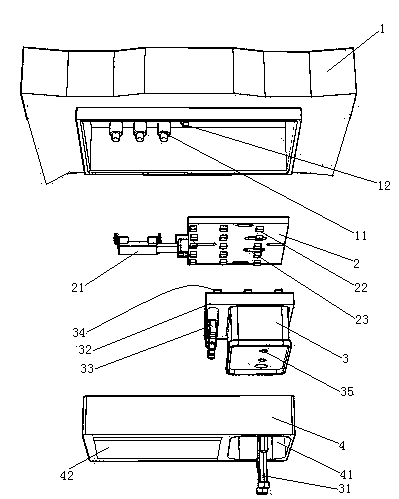
[0029] Embodiment one, see figure 1 , an automobile bridge roof cover mold, including an upper mold base 1, a movable push plate 2, a sunroof puncher 3, a suspension bolt 31 and a binder plate 4.

[0030] The upper mold base 1 is provided with a second gas spring 11 extending vertically. There are three second gas springs 11 . The upper mold base 1 is also provided with a positioning protrusion 12 .

[0031] The plane where the movable push plate 2 is located extends along the horizontal direction. The left end of movable push plate 2 is connected with switching cylinder 21. The switching cylinder 21 extends in the left-right direction. The lower surface of the movable push plate 2 is provided with a first jacking projection 22 . The first lifting protrusions 22 have three rows and are distributed along the left and right directions. There are five first jacking bumps in each row of first jacking bumps 22 . The first lifting bump 22 is provided with a strip-shaped via h...

Embodiment 2

[0037] Embodiment two, the difference with embodiment one is:

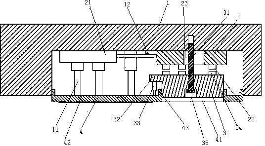
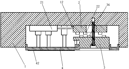
[0038] see Figure 4 , On the upper mold base 1, a push rod 5 is also worn. The push rod 5 can move forward and backward (perpendicular to the paper direction) and left and right. A connecting block 24 is arranged between the movable push plate 2 and the push rod 5 . The connecting block 24 connects the movable push plate 2 and the push rod 5 together.

[0039] The sunroof punch 3 comprises an upper half 36 and a lower half 37 . The upper half 36 and the lower half 37 are overlapped together in the vertical direction.

[0040] see Figure 5 , the first jacking bump 22 and the second jacking bump 34 are elongated structures. The first jacking bump 22 and the second jacking bump 34 are parallel. The extending direction of the first lifting protrusion 22 is perpendicular to the telescoping direction of the switching cylinder.

[0041] The connecting hole 35 is composed of an upper section 351 (the upper secti...

Embodiment 3

[0055] Embodiment three, the difference with embodiment two is:

[0056] see Figure 7 , also includes refueling device 9. The refueling device 9 includes an oil storage tank 91 , an oil outlet channel 92 , a membrane rupture rod 93 , a corrosive liquid storage tank 94 , a periodic rotting buoy 95 and a guide rod 96 .

[0057] The oil storage tank 91 is connected together with the regularly putrefying formula buoy 95 by a connecting rod 98 . The connecting rod 98 and the regular rotting buoy 95 are detachably connected together by bolts. The oil storage tank 91 includes at least two cavities 911 which in this embodiment are four cavities 911 which are sequentially sleeved and fixed together. Lubricating oil is housed in the cavity 911 (not shown in the lubricating oil figure). The lower wall of the cavity 911 is provided with an oil outlet 912 . The oil outlet 912 is sealed and connected with a sealing membrane 913 . A total of 4 oil outlets 912 of the 4 cavities are loca...


PUM


Abstract

The invention relates to vehicle production equipment, in particular to a bridge vehicle top cover die comprising an upper die seat, a skylight punch and a pressure plate. The upper die seat is provided with a movable push plate and a switching cylinder driving the movable push plate to move horizontally; the skylight punch is connected onto the upper die seat in a lifting manner, the movable push plate is located between the upper die seat and the skylight punch, the lower surface of the movable push plate is provided with a first ejecting projection, the upper end face of the skylight punch is provided with a second ejecting projection matching with the first ejecting projection, the skylight punch is provided with a first air spring extending vertically, the first air spring is connected to the pressure plate, the lower surface of the pressure plate is provided with a rubber layer, and the skylight punch penetrates the pressure plate. The bridge vehicle top cover die is capable of meeting the requirements of producing top covers with skylight and without skylight, and the defects that the top covers with skylight and without skylight of vehicles in the same specification is produced through two sets of dies is solved.

Description

technical field [0001] The invention relates to equipment for automobile production, in particular to a mold for a bridge car roof. Background technique [0002] Automobile is a common means of transportation in daily life. The car body (hereinafter referred to as car body) is provided with a car roof. There are two production methods for the car roof: one is casting and forming by mold, in the Chinese patent application number 2012104846763, the publication date is February 13, 2013, and the name is "a production process for fiber reinforced composite car roof". In the patent document of ", a method of making a car roof through a pouring process is disclosed; the other is to punch out a car roof through a stamping die, in China Patent Application No. 2011104538946, the publication date is July 3, 2013, A patent document titled "A Drawing Die for Auto Roof Parts" discloses a die and method for producing an auto roof by stamping. [0003] When the existing roof is inst...

Claims


Application Information

Patent Timeline
Patent Type & Authority Applications(China)
IPC IPC(8): B21D37/02B21D37/18
Inventor 危金兰
Owner 泰州英格伟精密机械有限公司
Why Eureka
Try Eureka