Material collecting mechanism of sanding machine
A technology of sanding machine and material rack, which is applied in the field of plate processing, can solve the problems that the spiral plate heat exchanger is fragile and cannot meet the needs of large production, and achieves the effect of facilitating forklift loading and transporting plates
- Summary
- Abstract
- Description
- Claims
- Application Information
AI Technical Summary
Problems solved by technology
Method used
Image

Examples
Embodiment Construction
[0024] In order to have a further understanding and understanding of the structural features of the present invention and the achieved effects, the preferred embodiments and accompanying drawings are used for a detailed description, as follows:
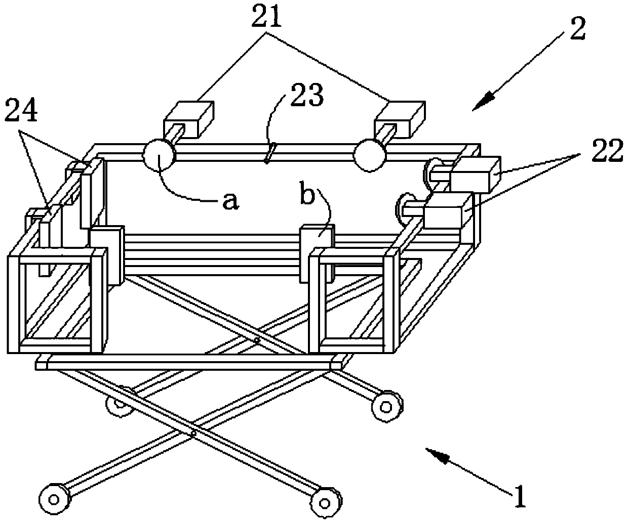
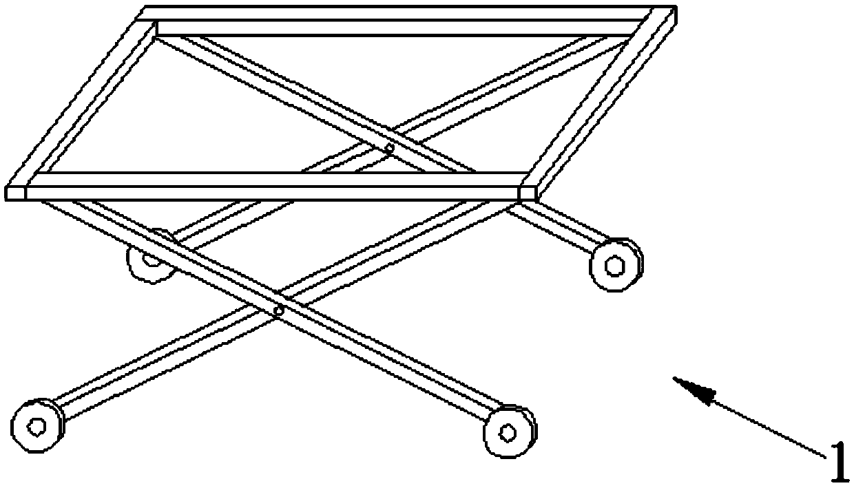
[0025] Such as figure 1 , image 3 As shown, a material receiving mechanism of a sander is arranged at the discharge end of the sander. The material receiving mechanism includes a lifting device 1 and a material receiving rack 2 . The lifting device 1 provided by the present invention is a lift. The receiving frame 2 has a cavity for accommodating plates; the lifting device 1 is located in the cavity. The bottom of the material receiving rack 2 provided by the present invention begins to have a space for accommodating the lifting device below the ground. That is, the receiving frame is fixed on the ground, and the lifting device 1 is below the ground (not shown).
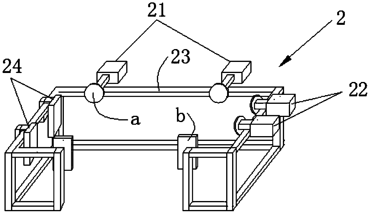
[0026] Such as figure 2 As shown, the receiving frame 2 is prov...
PUM
 Abstract
Description
Claims
Application Information
 - R&D
- Intellectual Property
- Life Sciences
- Materials
- Tech Scout
- Unparalleled Data Quality
- Higher Quality Content
- 60% Fewer Hallucinations
Browse by: Latest US Patents, China's latest patents, Technical Efficacy Thesaurus, Application Domain, Technology Topic, Popular Technical Reports.
© 2025 PatSnap. All rights reserved.Legal|Privacy policy|Modern Slavery Act Transparency Statement|Sitemap|About US| Contact US: help@patsnap.com