Rotary sewing material punching machine

A punching and sewing machine head technology, applied in the field of rotary punching machines, can solve the problems of low processing efficiency and many operation steps, and achieve the effect of improving punching efficiency

Active Publication Date: 2016-05-11
NINGBO SUPREME ELECTRONIC MASCH INC
View PDF6 Cites 8 Cited by
  • Summary
  • Abstract
  • Description
  • Claims
  • Application Information

AI Technical Summary

Problems solved by technology

When processing shoe uppers in the prior art, usually first measure the position of the opening on the upper sewing material, then manually open the hole, and then take the perforated sewing material to the sewing machine for sewing. There are many operating steps and the processing efficiency is low.

Method used


Image

  • Rotary sewing material punching machine
  • Rotary sewing material punching machine
  • Rotary sewing material punching machine

Examples


Embodiment Construction

[0019] Embodiments of the present invention will be described in further detail below in conjunction with the accompanying drawings.

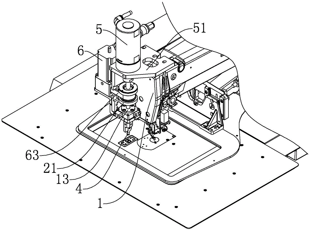
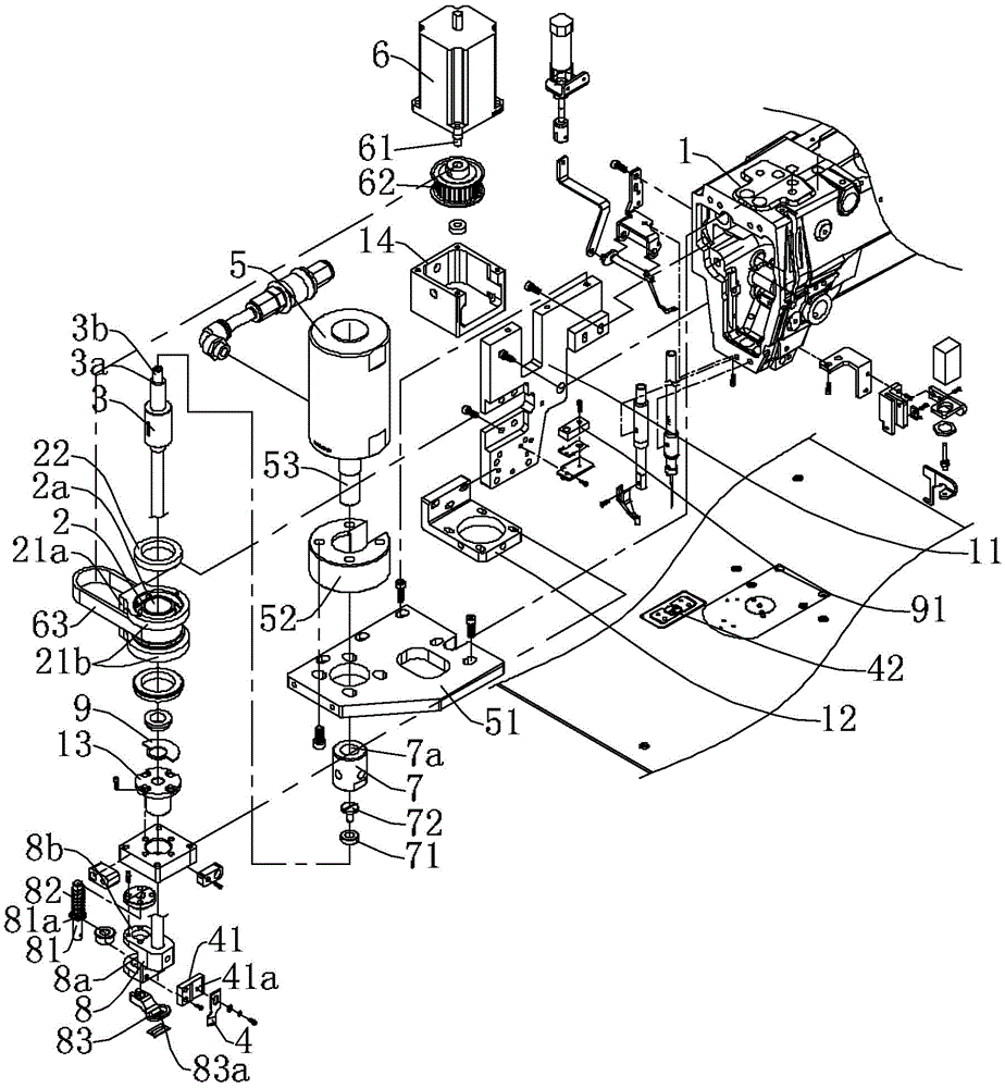
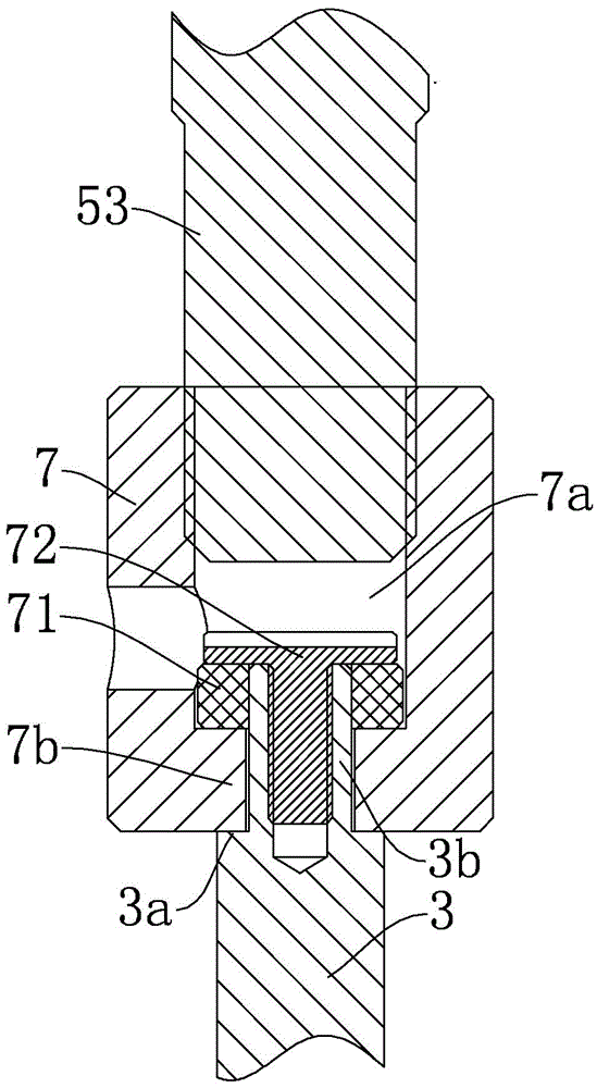
[0020] Figure 1 to Figure 3 Shown is the structural representation of the present invention.

[0021] Wherein the reference numerals are: sewing machine head 1, first mounting plate 11, guide sleeve mounting plate 12, guide sleeve 13, motor mounting plate 14, driven wheel 2, spline shaft sleeve 2a, driven wheel bracket 21, connecting plate 21a , mounting ring 21b, first bearing 22, spline transmission shaft 3, step surface 3a, step shaft 3b, punching knife 4, punching knife mounting seat 41, mounting groove 41a, punching knife bottom die 42, stamping cylinder 5, the second Mounting plate 51, cylinder mounting seat 52, piston rod 53, motor 6, power output shaft 61, active synchronous wheel 62, synchronous belt 63, transmission bushing 7, cavity 7a, plane bearing 71, fixing piece 72, presser foot installation Seat 8, first shaft sleeve 8a, sec...


PUM


Abstract

The invention discloses a rotary sewing material punching machine which comprises a sewing machine head. A rotatable driven wheel and a motor for driving the driven wheel to rotate through a transmission mechanism are installed on one side of the sewing machine head. A spline shaft sleeve is arranged at the axis of the driven wheel. A spline transmission shaft capable of moving axially is arranged in the spline shaft sleeve. A punching cylinder for driving the spline transmission shaft to axially move is arranged at the upper end of the spline transmission shaft. A punch is connected with the lower end of the spline transmission shaft. The rotary sewing material punching machine has a punching function and a sewing function; by controlling the rotating angle of the motor, the rotating angle of the punch can be adjusted, and therefore the angle of the punch is automatically adjusted, and the punch efficiency of sewing material is improved.

Description

technical field [0001] The invention relates to a sewing machine, in particular to a rotary punching machine capable of punching holes on sewing materials. Background technique [0002] In the field of sewing processing, some processes of opening holes in the sewing material and then sewing are often encountered. Such as the sewing process of vamp, at first needs to perforate on vamp, then puts webbing loop in hole, and webbing loop and vamp sewing are fixed, constitutes the shoelace loop that wears shoelace usefulness. When processing shoe uppers in the prior art, usually first measure the position of the opening on the upper sewing material, then manually open the hole, and then take the perforated sewing material to the sewing machine for sewing. There are many operating steps and low processing efficiency. Contents of the invention [0003] The technical problem to be solved by the present invention is to provide a rotary punching machine for the above-mentioned curre...

Claims


Application Information

Patent Timeline
Patent Type & Authority Applications(China)
IPC IPC(8): D05B37/02
CPCD05B37/02
Inventor 罗千
Owner NINGBO SUPREME ELECTRONIC MASCH INC
Why Eureka
Try Eureka