Hole punching and flanging punching mold

A stamping die and punching technology, applied in the direction of forming tools, manufacturing tools, metal processing equipment, etc., can solve the problems of inability to ensure high precision of workpieces, inability to obtain surface quality, increase production costs, etc., to achieve good stamping effect and mold structure Reasonable, the effect of improving production efficiency

Inactive Publication Date: 2016-05-25
TAICANG WANGMEI MOLD CO LTD
View PDF6 Cites 4 Cited by
  • Summary
  • Abstract
  • Description
  • Claims
  • Application Information

AI Technical Summary

Problems solved by technology

Because of the complexity of the workpiece, if the workpiece is operated in a single process, it will increase the difficulty of the next process. At the same time, the operation of this process will affect the accuracy of the previous process, which will seriously cause defects such as wrinkling and surface damage on the outer surface, and waste products. High efficiency, can not get a higher surface quality, but also increases the production cost, reduces the production efficiency, cannot guarantee the high precision of the workpiece

Method used


Image

  • Hole punching and flanging punching mold
  • Hole punching and flanging punching mold

Examples


Embodiment Construction

[0016] The present invention will be further described below in conjunction with the accompanying drawings.

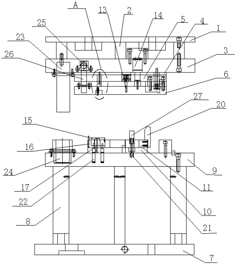
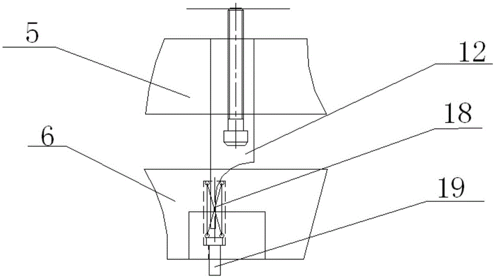
[0017] Such as figure 1 A stamping die for punching and extracting teeth is shown, including an upper die and a lower die. The upper die is sequentially connected with an upper supporting plate 1, an upper cushion block 2, an upper die base 3, an upper backing plate 4, and an upper splint 5 from top to bottom. And the upper stripping plate 6, the lower mold is connected with the lower supporting plate 7, the lower cushion block 8, the lower mold base 9, the lower backing plate 10 and the lower template 11 from bottom to top, and the punch 12 is fixedly installed on the upper clamping plate 5, punching The head 12 is connected with the spring a18 installed on the upper stripping plate, the lower end of the spring a18 is connected with the ejector pin 19, the upper splint 5 is also provided with a special-shaped punch 13, and the lower mold base 9 is provided with a nitr...


PUM


Abstract

The invention provides a hole punching and flanging punching mold, which comprises an upper mold and a lower mold, wherein the upper mold is sequentially connected with an upper support plate, an upper pad block, an upper mold seat, an upper pad plate, an upper clamp plate and an upper stripping plate from top to bottom; the lower mold is sequentially connected with a lower support plate, a lower pad block, a lower mold seat, a lower pad plate and a lower template from bottom to top; a punching head is fixedly arranged on the upper clamp plate, and is connected with a spring a arranged on the upper stripping plate; the lower end of the spring a is connected with a material jacking pin; a special-shaped punching element is also arranged on the upper clamp plate; a nitrogen gas spring a is arranged on the lower mold seat, and is connected with a lower template entering plate a arranged on the lower template; a flanging punching element is arranged on the lower mold seat, and sequentially passes through the lower pad plate and the lower template; a spring b is also arranged on the lower mold seat; the spring b is connected with a lower template entering block b. The mold provided by the invention has the advantages that the structure is reasonable; the functions of hole punching, flanging and shaping are realized; meanwhile, the punching effect is good; the precision is high; the process requirements and the shaping effect of the workpiece are ensured; the defect rate is effectively reduced; the production efficiency is improved; the production cost is reduced.

Description

technical field [0001] The invention relates to a stamping die, in particular to a stamping die for punching and extracting teeth. Background technique [0002] With the continuous improvement of the quality of industrial products, the variety, small batch, complex and large-scale precision of mold products are rapidly updated. Mold design and technology Due to manual equipment, relying on manual experience and conventional machining, the technology has changed to computer-aided design, NC programming chip processing, and computer-aided design technology with the core of NC electric machining. The high precision, high complexity, high productivity, high consistency and consumption of mold production parts can not be fully displayed in other manufacturing and processing, so it has good economic benefits, so it is widely used in mass production , has a very important position in modern industrial production, and is an indispensable processing method in my country's national de...

Claims


Application Information

Patent Timeline
Patent Type & Authority Applications(China)
IPC IPC(8): B21D37/10
CPCB21D37/10
Inventor 张忍
Owner TAICANG WANGMEI MOLD CO LTD
Why Eureka
Try Eureka