Woolen sweater dyeing machine

A technology for dyeing machines and woolen sweaters, which is applied in the field of woolen sweater dyeing machines, can solve problems such as inability to take out from the feed port, poor performance, and knotting of woolen sweaters, so as to reduce the use and discharge of dyeing wastewater , Stable use performance, and the effect of improving use performance

Inactive Publication Date: 2016-05-11
TONGXIANG NEW ERA FUR
View PDF3 Cites 19 Cited by
  • Summary
  • Abstract
  • Description
  • Claims
  • Application Information

AI Technical Summary

Problems solved by technology

[0002] Existing woolen sweaters are dyed by dyeing vats, etc. This kind of dyeing process needs to consume a lot of water resources and generate a lot of waste water
When using a rotary drum to dye it, although the water consumption is greatly reduced, the woolen sweater will be knotted...

Method used


Image

  • Woolen sweater dyeing machine
  • Woolen sweater dyeing machine
  • Woolen sweater dyeing machine

Examples


Embodiment 1

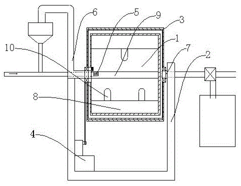
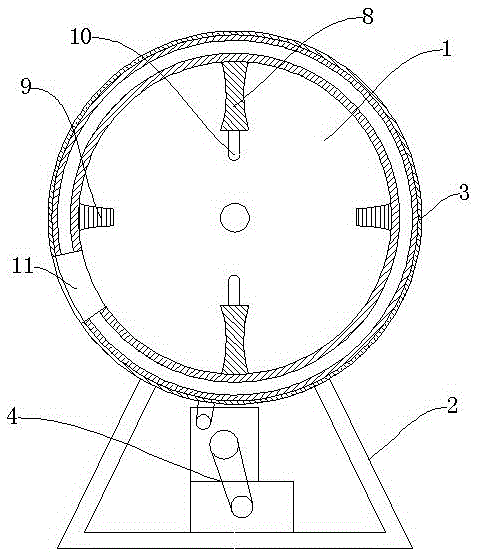
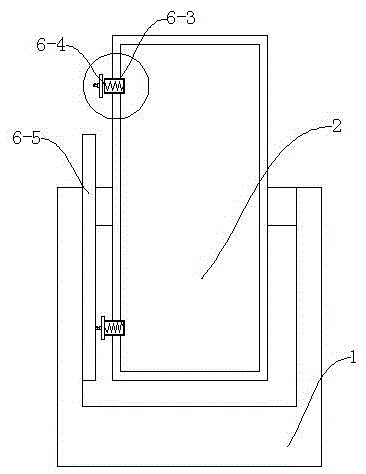
[0024] Such as figure 1 , figure 2 As shown, the woolen sweater dyeing machine described in this embodiment includes a frame 2, on which a drum 1 is arranged, and the two ends of the drum 1 are rotationally connected with the frame 2, and the drum 1 The outside of the body is covered with a layer of outer shell 3, and the drum 1 is fixedly connected with the outer shell 3, and there is a gap between the two; the frame 2 is provided with a power mechanism 4 that is connected to the drum 1 in transmission, and the machine The frame 2 is provided with a dye atomization mechanism 5, an air pressure balance mechanism 6 and a steam heating mechanism 7; the dye atomization mechanism 5 and the air pressure balance mechanism 6 are all communicated with the inside of the drum 1, and the steam heating mechanism 7 is connected with the The gap between the drum 1 and the outer casing 3 is connected; two main baffles 8 are arranged at intervals on the inner wall of the drum 1, and a secon...

Embodiment 2

[0027]The woolen sweater dyeing machine described in this embodiment includes a frame 2, on which a drum 1 is arranged, the two ends of the drum 1 are rotationally connected with the frame 2, and the drum 1 is wrapped A layer of outer shell 3 is covered, and the drum 1 is fixedly connected with the outer shell 3, and there is a gap between the two; a power mechanism 4 connected to the drum 1 is provided on the frame 2, and A dye atomization mechanism 5, an air pressure balance mechanism 6 and a steam heating mechanism 7 are provided; the dye atomization mechanism 5 and the air pressure balance mechanism 6 are all connected to the inside of the drum 1, and the steam heating mechanism 7 is connected to the drum 1 It communicates with the gap between the outer casing 3; three main baffles 8 are arranged at intervals on the inner wall of the drum 1, and a secondary baffle 9 is arranged between adjacent main baffles 8, and the main baffle 8 and The axial length of the auxiliary baf...


PUM


Abstract

The invention relates to the field of dyeing equipment, in particular to a woolen sweater dyeing machine. The woolen sweater dyeing machine comprises a machine frame, wherein a rotary drum is arranged on the machine frame, the outside of the rotary drum is wrapped with a layer of outer housing, a power mechanism in driving connection with the rotary drum is arranged on the machine frame, and a dye atomization mechanism, an air pressure balancing mechanism and a steam heating mechanism are arranged on the machine frame. Two main baffles are arranged on the inner wall of the rotary drum at an interval, an auxiliary baffle is arranged between the adjacent main baffles, and one or more radial shifting rods are arranged on the radial end face of each main baffle. A feeding door is arranged on the rotary drum between one group of adjacent main baffles and the auxiliary baffle and on the outer housing. The woolen sweater dyeing machine is simple in structure, can effectively utilize the rotary drum to dye woolen sweaters, does not cause a knitting phenomenon, is stable in using performance and reduces the using amount of water for dyeing and discharge of dyeing wastewater.

Description

technical field [0001] The invention relates to the field of dyeing equipment, in particular to a sweater dyeing machine. Background technique [0002] Existing woolen sweaters are dyed by dyeing vats, which consume a large amount of water resources and generate a large amount of waste water during the dyeing process. When using a rotary drum to dye it, although the water consumption is greatly reduced, the woolen sweater will be knotted after dyeing, especially between the sleeves, so that the woolen sweater in the drum is integrated and cannot be dyed. If it is taken out from the feed port, it will cause the dyeing to produce color spots, resulting in poor performance and difficult to use in large-scale dyeing. Contents of the invention [0003] The purpose of the present invention is to provide a simple structure, which can effectively realize the dyeing of woolen sweaters and other garments in the drum, and avoid knotting. [0004] In order to achieve the above objec...

Claims


Application Information

Patent Timeline
IPC IPC(8): D06B3/30D06B23/18
CPCD06B3/30D06B23/18
Inventor 徐建龙
Owner TONGXIANG NEW ERA FUR
Why Eureka
Try Eureka