Locking device

A lock device and lock cylinder technology, which is applied in door/window accessories, wing leaf parts, building fastening devices, etc., can solve the problems of reducing the service life and wear of the lock device, so as to improve the service life and reduce wear , the effect of reducing friction

Active Publication Date: 2016-05-11
LIP HING YEUNGS IND SHENZHEN
View PDF6 Cites 3 Cited by
  • Summary
  • Abstract
  • Description
  • Claims
  • Application Information

AI Technical Summary

Problems solved by technology

[0002] In order to lock the window conveniently, a locking device is generally installed on the window. The locking device includes a cylindrical first locking cylinder and a second locking cylinder with a contact surface. The first locking cylinder is installed on the window sash, and the second The lock cylinder is installed on the window frame. When the window is closed or opened, the first lock cylinder moves linearly along the second lock cylinder until the window is closed or opened, that is, in the process of closing or opening the window, the first lock cylinder and the second lock cylinder There is always friction between the first lock cylinder and the second lock cylinder to be severely worn, which reduces the service life of the locking device

Method used


Image

  • Locking device
  • Locking device
  • Locking device

Examples


Embodiment Construction

[0027] The following will clearly and completely describe the technical solutions in the embodiments of the present invention with reference to the drawings in the embodiments of the present invention.

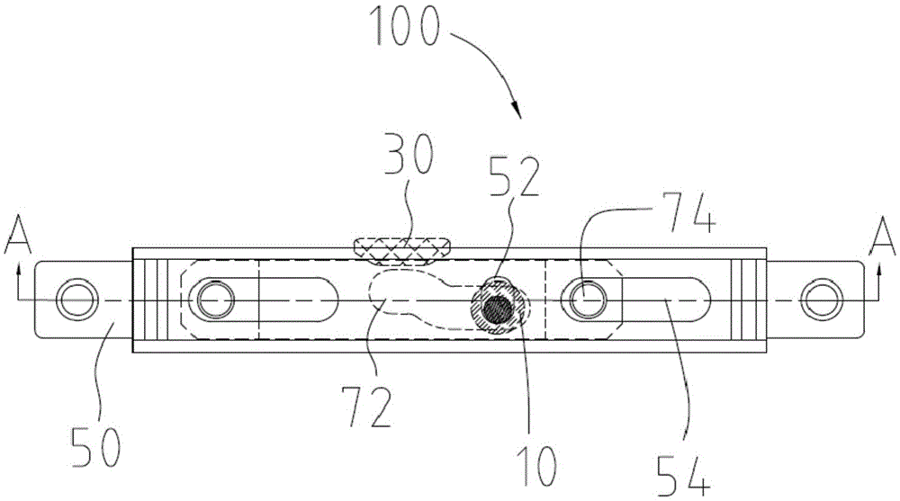
[0028] Please refer to figure 1 , is the locking device 100 provided in the first embodiment of the present invention, and is used for locking doors and windows.

[0029] In this embodiment, doors and windows refer to doors and windows of buildings, safe doors and furniture doors and windows, but are not limited thereto. In order to describe the aspect, a window is taken as an example below, and the window includes a sash and a window frame.

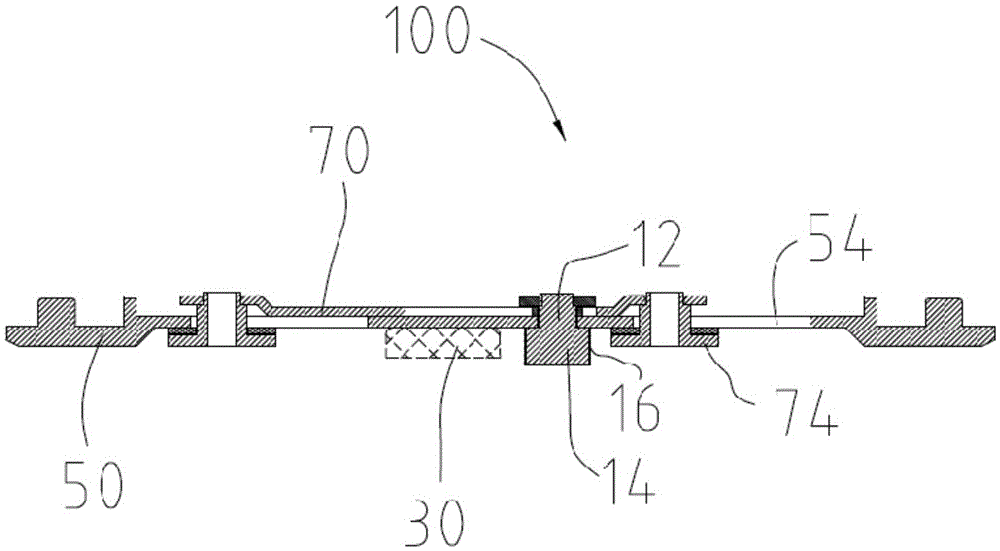
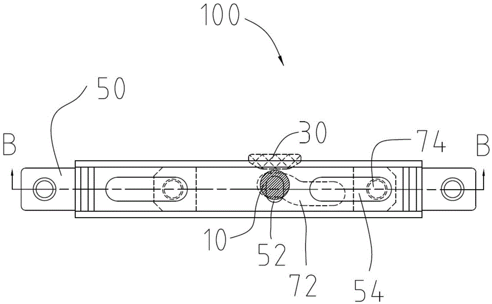
[0030] Please refer to Figure 1 to Figure 6 , the locking device 100 includes a first lock cylinder 10, a second lock cylinder 30, a movable part 50 and a fixed part 70, the fixed part 70 is provided with a displacement groove 72, and the movable part 50 is provided with a receiving groove 52 , the first lock cylinder 10 is movably c...


PUM


Abstract

The invention discloses a locking device which comprises a first locking cylinder, a second locking cylinder, movable parts and fixed parts. Moving grooves are formed in the fixed parts. Containing grooves are formed in the movable parts. The first locking cylinder is movably connected with the movable parts and is contained in the containing grooves and the moving grooves. The movable parts move in the first direction relative to the fixed parts. The first locking cylinder moves in the moving grooves along with the movable parts and the first locking cylinder moves in the second direction in the containing grooves so that the first locking cylinder and the second locking cylinder can be unlocked or locked, wherein the first direction is perpendicular to the second direction. According to the locking device, the relative movement of the movable parts and the fixed parts is used as the deflecting movement, friction is only generated between the first locking cylinder and the second locking cylinder in the locking state, friction between the first locking cylinder and the second locking cylinder is relieved, abrasion of the first locking cylinder and the second locking cylinder is relieved, the service life of the locking device is prolonged, and the problem of serious abrasion caused by constant friction due to linear movement between the first locking cylinder and the second locking cylinder in the prior art is solved.

Description

technical field [0001] The invention relates to a locking device. Background technique [0002] In order to lock the window conveniently, a locking device is generally installed on the window. The locking device includes a cylindrical first locking cylinder and a second locking cylinder with a contact surface. The first locking cylinder is installed on the window sash, and the second The lock cylinder is installed on the window frame. When the window is closed or opened, the first lock cylinder moves linearly along the second lock cylinder until the window is closed or opened, that is, in the process of closing or opening the window, the first lock cylinder and the second lock cylinder Friction has been generated between the first lock cylinder and the second lock cylinder to be severely worn, reducing the service life of the locking device. Contents of the invention [0003] The object of the present invention is to provide a durable locking device. [0004] In order to...

Claims


Application Information

Patent Timeline
IPC IPC(8): E05C19/00
CPCE05C19/00E05Y2900/148
Inventor 杨钟汉
Owner LIP HING YEUNGS IND SHENZHEN
Why Eureka
Try Eureka