Backlight module

A technology of backlight module and backplane, which is applied in the direction of optics, light source, point light source, etc., can solve the problem of not being able to meet the requirements of the backlight module, and achieve the effect of reducing the amount of materials used

Inactive Publication Date: 2016-05-11
CORETRONIC (SUZHOU) CO LTD
View PDF6 Cites 0 Cited by
  • Summary
  • Abstract
  • Description
  • Claims
  • Application Information

AI Technical Summary

Problems solved by technology

Because the diffusion plate 106 of the known backlight module 100 is a plate-shaped solid structure with a certain thickness, it cannot meet the current demand for lighter and thinner backlight modules.

Method used


Image

  • Backlight module
  • Backlight module
  • Backlight module

Examples


Embodiment Construction

[0016] The aforementioned and other technical contents, features and effects of the present invention will be clearly presented in the following detailed description of the embodiments with accompanying drawings. The directional terms mentioned in the following embodiments, such as: up, down, left, right, front or back, etc., are only referring to the directions of the drawings. Accordingly, the directional terms are used to illustrate and not to limit the invention.

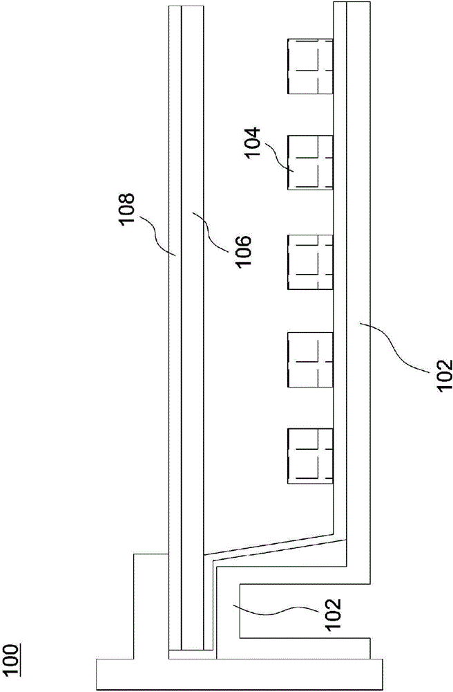
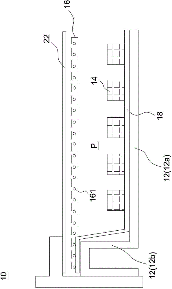
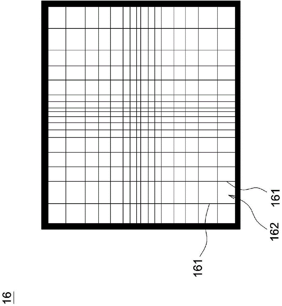
[0017] figure 2 It is a schematic partial cross-sectional view of a backlight module according to an embodiment of the present invention. Such as figure 2 As shown, a backlight module 10 includes a backplane 12 , at least one light source 14 , and a mesh diffusion structure 16 . The backplane 12 includes a baseboard 12a and a plurality of sidewalls 12b ( figure 2 Only one side wall 12b is shown in the figure, and the multiple side walls 12b are connected to the bottom plate 12a and form an accommodating s...


PUM


Abstract

The invention discloses a backlight module. The backlight module comprises a backboard, at least one light source and a net-shaped diffusion structure. The backboard comprises a bottom plate and a plurality of side walls connected to the bottom plate, and a containing space is defined by the side walls and the bottom plate. The net-shaped diffusion structure is arranged above the containing space and comprises a plurality of transparent cables, the transparent cables are interwoven to form a plurality of grids, and the net-shaped diffusion structure has different cable distribution densities in different zones. By means of the backlight module, the material using amount can be reduced, the requirement for the thin backlight module is met, and the manufacture procedure can be simplified.

Description

technical field [0001] The invention relates to a backlight module. Background technique [0002] figure 1 It is a partial cross-sectional schematic diagram of a known backlight module. Such as figure 1 As shown, the backlight module 100 has a backplane 102 , a light source 104 and a diffusion plate 106 confined in the backplane 102 , and at least one optical film 108 is disposed on the diffusion plate 106 . Because the diffuser plate 106 of the known backlight module 100 is a plate-shaped solid structure with a certain thickness, it cannot meet the current demand for lighter and thinner backlight modules. [0003] Taiwan Patent Publication No. TW201024809A discloses a diffuser plate, which includes a light emitting surface, a light incident surface, a plurality of main linear protrusions and a plurality of secondary linear protrusions. The light-incident surface and the light-exit surface are arranged oppositely, and the light diffusing ability can be improved by mixing...

Claims


Application Information

Patent Timeline
Patent Type & Authority Applications(China)
IPC IPC(8): F21V5/00G02B5/02G02F1/13357F21Y101/02
Inventor 刘绍凤
Owner CORETRONIC (SUZHOU) CO LTD
Why Eureka
Try Eureka