
A concrete tie rod arch bridge suspender lower anchor end connection structure and its construction method

A technology for tied arch bridges and connecting structures, applied in bridges, bridge parts, bridge construction, etc., can solve the problems of anchor end structure corrosion, inconvenient replacement of booms, breakage of booms, etc., to extend service life and strength, and facilitate real-time The effect of maintenance and avoidance of rust and aging

Active Publication Date: 2017-03-29
HUZHOU TRAFFIC PLANNING & DESIGN INST
View PDF1 Cites 0 Cited by
  • Summary
  • Abstract
  • Description
  • Claims
  • Application Information

AI Technical Summary

Problems solved by technology

[0002] The upper end of the suspender of the existing concrete tie-bar arch bridge is anchored on the arch rib, and the lower end of the suspender passes through the pre-buried pipe in the concrete tie beam and is buried inside the tie beam near the bottom edge. After the suspender is stretched, it is sealed with concrete. anchor, the entire structure is hidden inside the tie beam; this design has the following problems in the bridge operation process: the bridge is often in a state of vibration under the excitation of wind, rain, vehicles, etc. Under the action, water erosion is prone to occur in the anchorage area of ​​the lower anchor end of the suspender, and long-term water erosion will cause corrosion and fatigue of the anchor end structure, which may easily lead to breakage accidents of the suspender; It is difficult to check and maintain in the later stage, the danger is hidden and invisible, it is easy to cause damage without warning, there is a great potential safety hazard, and it is not convenient to replace the suspender
The concrete rigid suspenders of the concrete tie-rod arch bridge are equipped with fine-rolled threaded steel bars as prestressed steel bars, and the bearing load is low. The steel bars are corroded, seriously affecting the operational safety and service life of the bridge

Method used


Image

  • A concrete tie rod arch bridge suspender lower anchor end connection structure and its construction method
  • A concrete tie rod arch bridge suspender lower anchor end connection structure and its construction method
  • A concrete tie rod arch bridge suspender lower anchor end connection structure and its construction method

Examples


Embodiment 1

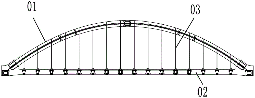
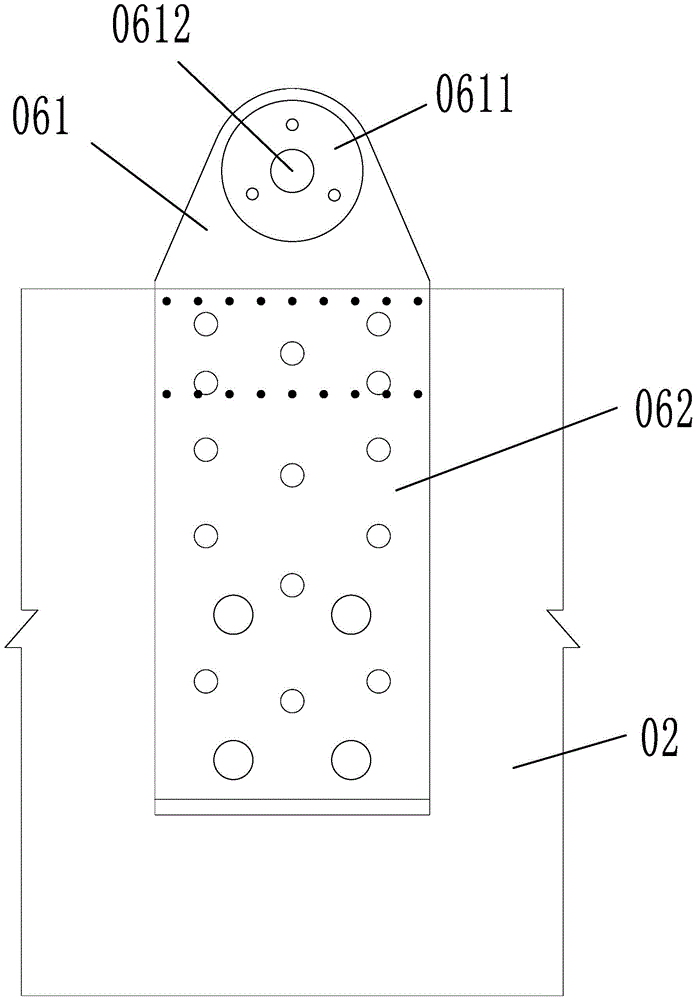
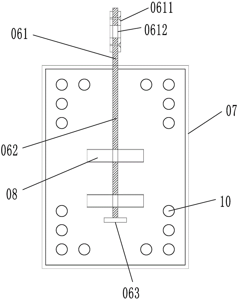
[0031] Embodiment 1: as figure 1 , 2 As shown, a concrete tie-bar arch bridge suspender lower anchor connection structure, the concrete tie-bar arch bridge includes: tie beam 02 and arch rib 01, tie beam and arch rib are provided with several suspenders 03, the arch rib is arc-shaped, The two ends of the arch rib are integrated with the tie beam, and the suspender is vertically connected between the arch rib and the tie beam. It also includes lug connector 06, which includes pouring part 062 and connecting part 061. The pouring part is poured in the tie beam, the connecting part protrudes above the tie beam, and the bottom of the suspender is hinged and fixed to the connecting part. Such as image 3 , 4 As shown, the pouring part has a rectangular plate-like structure, and the end of the pouring part far away from the connection part is provided with a transverse restraint plate 063 perpendicular to the pouring part, and the upper end of the pouring part is provided with a ...

Embodiment 2

[0035] Embodiment 2: The structure of this embodiment is basically the same as that of Embodiment 1, the difference is that, as Figure 9 As shown, the fixing holes 081 are evenly and densely distributed on the positioning pipe, and the bolts 082 are connected to the internal threads of the fixing holes. When the positioning pipe and the tie beam are strengthened, when the positioning pipe is subjected to tension, the bolts can enhance the connection strength between the tie beam and the positioning pipe, avoiding the misalignment of the positioning pipe and thus avoiding the dislocation of the pouring part.

Embodiment 3

[0036] Embodiment 3: The structure of this embodiment is basically the same as that of Embodiment 1 or Embodiment 2, the difference is that, as Figure 10 As shown, the spiral pipe 083 is pierced in the positioning pipe, and when the positioning pipe is filled with concrete, the spiral pipe and the positioning pipe are poured integrally, and the spiral pipe can enhance the connection strength between the positioning pipe and the tie beam pouring.


PUM


Abstract

The invention relates to an arch bridge structure, in particular to a connecting structure of anchorage ends of booms of a concrete tied arch bridge and a construction method of the connecting structure. The connecting structure of the anchorage ends of the booms of the concrete tied arch bridge comprises booms and a lug plate connecting fitting, wherein the lug plate connecting fitting comprises a pouring part and connecting part; the pouring part is poured in a tied beam; the connecting part is protruded above the tied beam; the bottoms of the booms are hinged and fixed to the connecting part, and a connecting arm is arranged at the bottoms of the booms; the connecting arm is connected with the connecting part of the lug plate connecting fitting. An upper preburied pipe penetrates through an arch rib, the upper ends of the booms penetrate through the upper preburied pipe to be connected with a tensioning device, and the tensioning device is compacted and fixed to a position above the arch rib. The connecting structure disclosed by the invention has the beneficial effects that an original concealed and invisible stress region is exposed to the upper edge of a concrete tied beam, the purpose that the booms are convenient to examine, and easy to maintain and exchange during the late curing of engineering can be realized, and the situation that the bridge is destroyed without warning caused by concealed damage generated at the anchorage ends of the booms can be fundamentally avoided.

Description

technical field [0001] The invention relates to an arch bridge structure, in particular to a connection structure of the lower anchor end of the suspender of a concrete tie-rod arch bridge and a construction method thereof. Background technique [0002] The upper end of the suspender of the existing concrete tie-bar arch bridge is anchored on the arch rib, and the lower end of the suspender passes through the pre-buried pipe in the concrete tie beam and is buried inside the tie beam near the bottom edge. After the suspender is stretched, it is sealed with concrete. anchor, the entire structure is hidden inside the tie beam; this design has the following problems in the bridge operation process: the bridge is often in a state of vibration under the excitation of wind, rain, vehicles, etc. Under the action, water erosion is prone to occur in the anchorage area of ​​the lower anchor end of the suspender, and long-term water erosion will cause corrosion and fatigue of the anchor...

Claims


Application Information

Patent Timeline
Patent Type & Authority Patents(China)
IPC IPC(8): E01D19/00E01D19/14
CPCE01D19/00E01D19/14
Inventor 陆树荣刘厚平宋恭俭张启标江越胜周晖熊峰伟仵云飞李玲芳刘春山
Owner HUZHOU TRAFFIC PLANNING & DESIGN INST
Learn More