
Gas cushion sealing bolts for gas insulated switchgear

A gas-insulated switch and equipment technology, which is applied in the setting of switchgear, switchgear, mechanical equipment, etc., can solve the problems of low rust and anti-corrosion technology, loose and aggravated glass glue, and prevent rust, aging and gas. Penetration, reduce the corrosion of iron structure, improve the effect of economic benefits

Active Publication Date: 2015-11-11
STATE GRID CORP OF CHINA +1
View PDF8 Cites 0 Cited by
  • Summary
  • Abstract
  • Description
  • Claims
  • Application Information

AI Technical Summary

Problems solved by technology

The disadvantage of this bolt connection state structure is that there is no sealing measure at the bolt body 1 of the crimped upper flange 10, lower flange 12, and insulating basin 141, and is exposed to air for a long time, so it is easy to corrode and age. In severe cases, it will lead to gas leakage inside the equipment gas chamber, which in turn will cause the consequences of equipment leakage
especially in CO 2 Under harsh environmental conditions such as serious pollution gas pollution and high terrain, the glass glue is aging and loose, and dust and rainwater enter the bolt crimping part of the equipment along with the gap. The aging of outdoor GIS equipment in substations is more serious
Running for a long time under harsh environmental conditions, it is easy to rust at the water inlet part of the bolt gap. With the continuous entry of dust and rain, the corrosion of the water inlet part will continue to increase. The iron oxide produced after iron rust will Continuous expansion, resulting in insufficient compression of the sealing rubber ring of the equipment, unable to play the proper sealing role
According to the search, there is no bolt that is sealed by the air cushion and buckled the cover.

Method used


Image

  • Gas cushion sealing bolts for gas insulated switchgear
  • Gas cushion sealing bolts for gas insulated switchgear
  • Gas cushion sealing bolts for gas insulated switchgear

Examples


Embodiment Construction

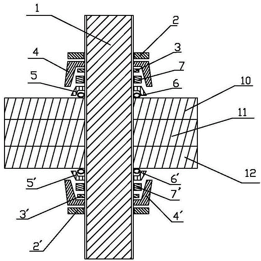
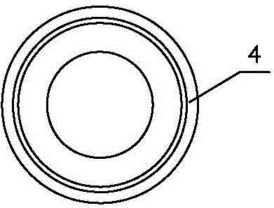
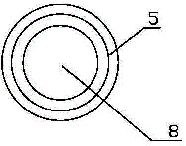
[0015] refer to figure 1 , figure 2 , image 3 , Figure 4 Make the invention. The gas-insulated switchgear uses an air cushion to seal the bolt, including the bolt body 1, the upper first layer of nut 2, the upper elastic washer 3, the lower end of the first layer of nut 2', the lower end of the elastic washer 3', the upper end of the first layer of nut 2 Rotate on the upper end of the bolt body 1, the upper elastic washer 3 is set on the bolt body 1 inside the upper first layer nut 2; the lower end first layer nut 2' rotates on the lower end of the bolt body 1, and the lower elastic washer 3' is set On the bolt body 1 inside the first layer of nuts 2' at the lower end; the middle part is a fastened upper flange 10, an insulating basin 11 and a lower flange 12, which is characterized in that: the first layer of nuts at the upper end The bolt body 1 between 2 and the elastic washer 3 at the upper end is provided with the first layer of insulating open basin-shaped button...


PUM


Abstract

The invention discloses a cushion seal bolt for gas insulated switchgear. The cushion seal bolt comprises a bolt body, first-layer nuts and elastic gaskets. The first-layer nuts are arranged at the ends of the bolt body in a screwed mode. The positions, on the inner sides of the first-layer nuts, of the bolt body are sleeved with the elastic gaskets. The cushion seal bolt for the gas insulated switchgear is characterized in that the positions, between the first-layer nuts and the elastic gaskets, of the bolt body are provided with first-layer basin-shaped insulating open covers; second-layer basin-shaped insulating open covers are arranged in the first-layer basin-shaped insulating open covers; annular gas bag cushions are arranged in the second-layer basin-shaped insulating open covers; second-layer nuts are arranged on the outer sides of the second-layer basin-shaped insulating open covers. The bolt can be effectively in compression connection with a connection component, in addition, connection gaps are sealed through the annular gas bag cushions, the bolt is compressed through the two layers of basin-shaped insulating open covers and the nuts, and therefore rusting and ageing of the compression connection component and gas penetration can be effectively prevented.

Description

technical field [0001] The invention relates to an improvement of a connecting bolt for a gas-insulated switchgear, in particular to an air-cushion sealing bolt for a gas-insulated switchgear. Background technique [0002] In the gas insulated switchgear (GIS equipment) in the substation, insulating pots and upper and lower flanges are used to isolate the gas chambers between the gas chambers, and bolts are used between the equipment shell and the insulating basin used to isolate the gas chambers. Crimping and sealing, tightening by bolts The insulating basin is the main connecting part on the gas insulated switchgear, and its connection state structure is as follows Figure 5 Shown: including bolt body 1, nut 2, washer 3, upper flange 10, lower flange 12, insulating basin 11, nut 2 rotates at both ends of bolt body 1, and the inner side of nut 2 is provided with The washer 3, the middle part of the bolt body 1 is a fastened upper flange 10, an insulating basin 11 and a lowe...

Claims


Application Information

Patent Timeline
Patent Type & Authority Patents(China)
IPC IPC(8): H02B13/045F16B37/00
Inventor 宋建国程鹏赵希希张文娟姚松涛刘国庆张爱明韩荣鑫赵萌任维锋郭俊春
Owner STATE GRID CORP OF CHINA
Learn More