Divider pulling material structure
A drainage groove and body technology, which is applied in the field of the material pulling structure of the shunt nozzle, can solve problems such as deformation, and achieve the effects of preventing deformation, improving quality and stabilizing the mold.
- Summary
- Abstract
- Description
- Claims
- Application Information
AI Technical Summary
Problems solved by technology
Method used
Image
Examples
Embodiment 1
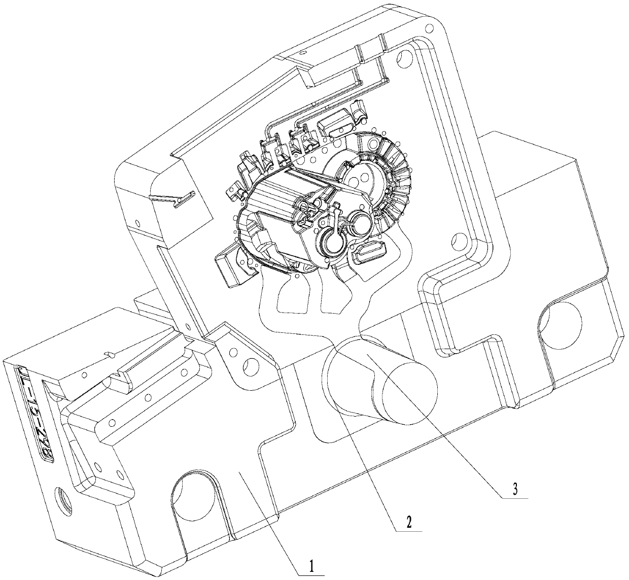
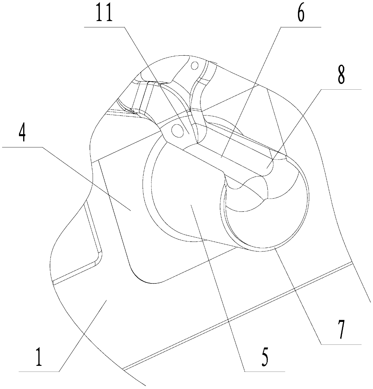
[0021] Embodiment 1: A kind of shunt nozzle pulling material structure (see attached figure 1 , attached figure 2 ), including the fixed mold frame 1, the shunt nozzle 2 installed on the fixed mold frame, the product material handle 3 is arranged between the shunt nozzle and the fixed mold frame, and the shunt nozzle includes a base 4 and a shunt nozzle arranged on the base The body 5 has a rectangular base, and the diverter nozzle is arranged vertically on the base. The body of the diverter nozzle is in the shape of a circular platform with a small upper part and a larger lower part. There is a drainage groove 6 on the side wall of the diverter nozzle body. There is a circle of holding groove 7 on the edge of the upper surface of the diversion nozzle body. Both ends of the holding groove are connected with the drainage groove. , the angle between the sides and the bottom of the holding groove is 88-92 degrees. The axial height of the holding groove from the upper surface o...
Embodiment 2
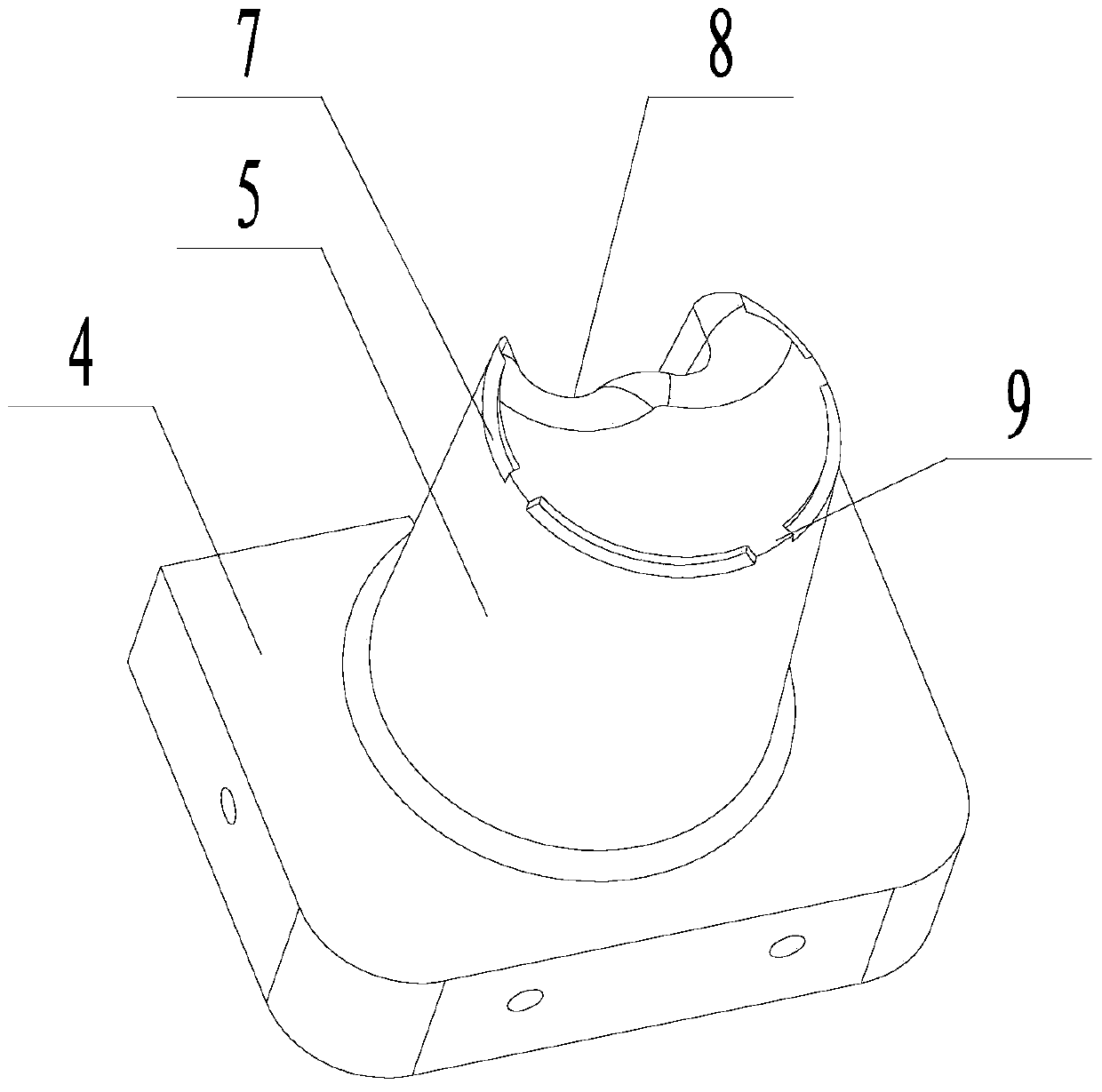
[0023] Embodiment 2: A kind of shunt nozzle pulling material structure (see attached image 3 ), including the fixed mold frame 1, the shunt nozzle 2 installed on the fixed mold frame, the product material handle 3 is arranged between the shunt nozzle and the fixed mold frame, and the shunt nozzle includes a base 4 and a shunt nozzle arranged on the base The body 5 has a rectangular base, and the diverter nozzle is arranged vertically on the base. The body of the diverter nozzle is in the shape of a circular platform with a small upper part and a larger lower part. There is a drainage groove 6 on the side wall of the diverter nozzle body. There is a circle of holding groove 7 on the edge of the upper surface of the diversion nozzle body. Both ends of the holding groove are connected with the drainage groove. , the angle between the sides and the bottom of the holding groove is 88-92 degrees. The axial height of the holding groove from the upper surface of the diverter body to...
Embodiment 3
[0024] Embodiment 3: A kind of shunt nozzle pulling material structure (see attached image 3 ), including the fixed mold frame 1, the shunt nozzle 2 installed on the fixed mold frame, the product material handle 3 is arranged between the shunt nozzle and the fixed mold frame, and the shunt nozzle includes a base 4 and a shunt nozzle arranged on the base The body 5 has a rectangular base, and the diverter nozzle is arranged vertically on the base. The body of the diverter nozzle is in the shape of a circular platform with a small upper part and a larger lower part. There is a drainage groove 6 on the side wall of the diverter nozzle body. There is a circle of holding groove 7 on the edge of the upper surface of the diversion nozzle body. Both ends of the holding groove are connected with the drainage groove. , the angle between the sides and the bottom of the holding groove is 88-92 degrees. The axial height of the holding groove from the upper surface of the diverter body to...
PUM
| Property | Measurement | Unit |
|---|---|---|
| height | aaaaa | aaaaa |
| width | aaaaa | aaaaa |
Abstract
Description
Claims
Application Information
 - R&D
- Intellectual Property
- Life Sciences
- Materials
- Tech Scout
- Unparalleled Data Quality
- Higher Quality Content
- 60% Fewer Hallucinations
Browse by: Latest US Patents, China's latest patents, Technical Efficacy Thesaurus, Application Domain, Technology Topic, Popular Technical Reports.
© 2025 PatSnap. All rights reserved.Legal|Privacy policy|Modern Slavery Act Transparency Statement|Sitemap|About US| Contact US: help@patsnap.com


