
Wideband microwave antenna feed

A microwave antenna, broadband technology, applied in the directions of antennas, electrical components, etc., to achieve the effect of simple and reasonable structure and broad application prospects

Inactive Publication Date: 2011-03-30
TONGYU COMM INC
View PDF2 Cites 7 Cited by
  • Summary
  • Abstract
  • Description
  • Claims
  • Application Information

AI Technical Summary

Problems solved by technology

[0003] like Figure 5 As shown, the feed source of a conventional feed-back microwave antenna is generally composed of a circular waveguide, a dielectric block, and a metal secondary reflector. The design of a microwave antenna generally requires that the standing wave ratio is less than 1.3 and the antenna efficiency is greater than 60%. The conventional feed-back Microwave antennas can only meet the requirements within 10% of the bandwidth

Method used


Image

  • Wideband microwave antenna feed
  • Wideband microwave antenna feed
  • Wideband microwave antenna feed

Examples


Embodiment Construction

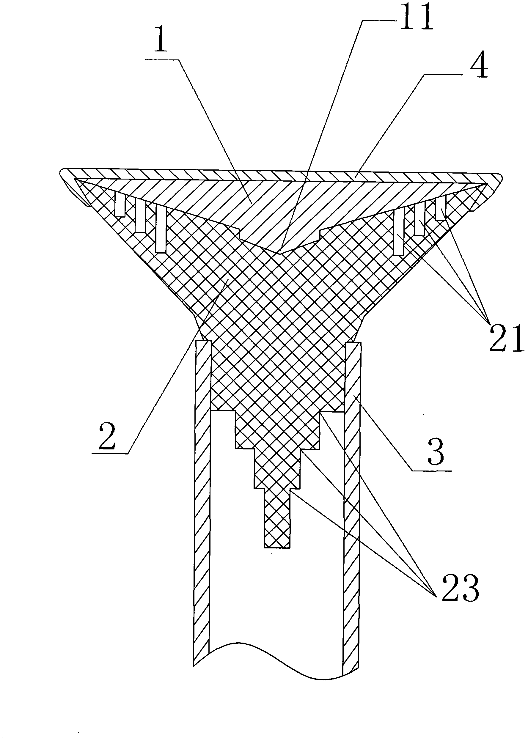
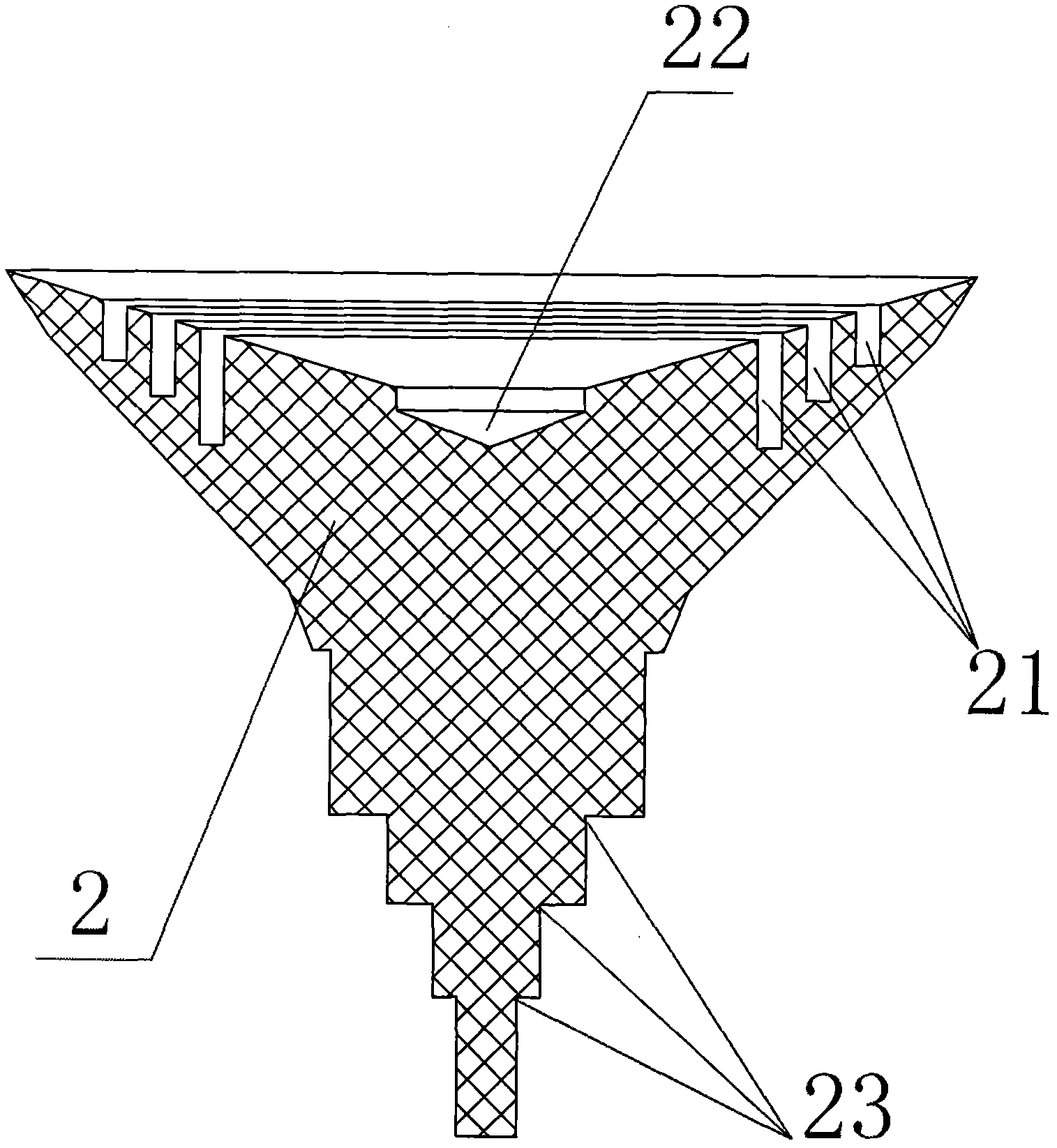
[0024] refer to figure 1 , figure 2 , image 3 with Figure 4 , a broadband microwave antenna feed source, including a metal sub-reflector 1, a dielectric block 2 and a circular waveguide 3, the metal sub-reflector 1 is connected to the circular waveguide 3 through a dielectric block 2, and the three are about the same central axis Symmetrically, the top of the dielectric block 2 is provided with a coaxial annular groove 21 and a tapered groove 22 , and the bottom of the metal secondary reflector 1 is provided with a matching cone 11 corresponding to the tapered groove 22 .

[0025] As a preferred embodiment of the present invention, the contour broken line of the matching cone 11 cut to its longitudinal section is divided into four sections, which are symmetrical about the central axis.

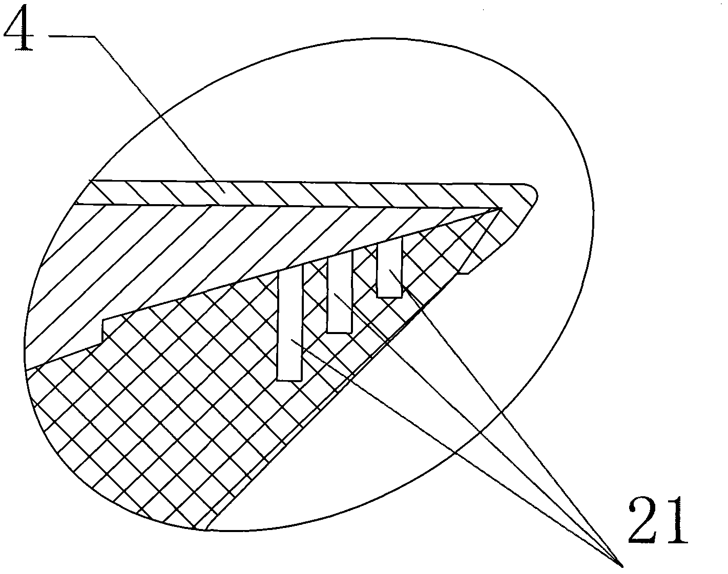
[0026] The metal sub-reflecting surface 1 and the dielectric block 2 are tightly fixed by the injection molded part 4, the number of coaxial annular grooves 21 provided on the dielectri...


PUM


Abstract

The invention discloses a wideband microwave antenna feed comprising a metal subreflecting surface, a medium block and a circular waveguide pipe, wherein the metal subreflecting surface is connected with the circular waveguide pipe by the medium block; the metal subreflecting surface, the medium block and the circular waveguide pipe are symmetrical corresponding to the same axial line, the top of the medium block is provided with a coaxial annular groove and a conical groove, and the corresponding position of the bottom of the metal subreflecting surface and the conical groove is provided with a matching taper. Because the structures of the medium block and the metal subreflecting surface are moulded, the upper part of the medium block is provided with the conical groove and at least one annular groove, and the bottom pf the metal subreflecting surface is provided with the matching taper corresponding to the conical groove in order to increase a variable factor of the feed; when passing through a circular step, electromagnetic waves can enter the medium block according to a certain mode proportion, then, the matching taper, the conical groove and the annular groove are mutually coordinated to regulate the amplitude and the phase of the electromagnetic waves, the effective bandwidth of the microwave antenna achieves about 20 percent, and the wideband microwave antenna feed has better popularizing and using values.

Description

technical field [0001] The invention relates to the technical field of microwave antennas, in particular to a broadband microwave antenna feed source. Background technique [0002] The microwave antenna is an important part of the microwave relay communication system. The broadband microwave antenna can better meet the needs of the project. The feed source is the core of the entire microwave antenna. Design a feed source with wide frequency band, superior performance and reliable structure It has always been expected. [0003] Such as Figure 5 As shown, the feed source of a conventional feed-back microwave antenna is generally composed of a circular waveguide, a dielectric block, and a metal secondary reflector. The design of a microwave antenna generally requires that the standing wave ratio is less than 1.3 and the antenna efficiency is greater than 60%. The conventional feed-back Microwave antennas can only meet the requirements within 10% of the bandwidth. [0004] Th...

Claims


Application Information

Patent Timeline
Patent Type & Authority Applications(China)
IPC IPC(8): H01Q13/00H01Q15/14
Inventor 阳恩主冯晨波
Owner TONGYU COMM INC
Learn More