Method of estimating brake pad wear and vehicle having a controller that implements the method

A technology of brake pads and brake rotors, applied in the direction of brake types, vehicle components, brake safety systems, etc., which can solve the problems of inconvenient inspection of brake pads and prolonged parking time.

Active Publication Date: 2016-05-25
GM GLOBAL TECH OPERATIONS LLC
View PDF7 Cites 14 Cited by
  • Summary
  • Abstract
  • Description
  • Claims
  • Application Information

AI Technical Summary

Problems solved by technology

It is inconvenient to visually inspect the brake pads during the track phase, because then the "refuel (or service) stop" time is prolonged

Method used


Image

  • Method of estimating brake pad wear and vehicle having a controller that implements the method
  • Method of estimating brake pad wear and vehicle having a controller that implements the method
  • Method of estimating brake pad wear and vehicle having a controller that implements the method

Examples


Embodiment Construction

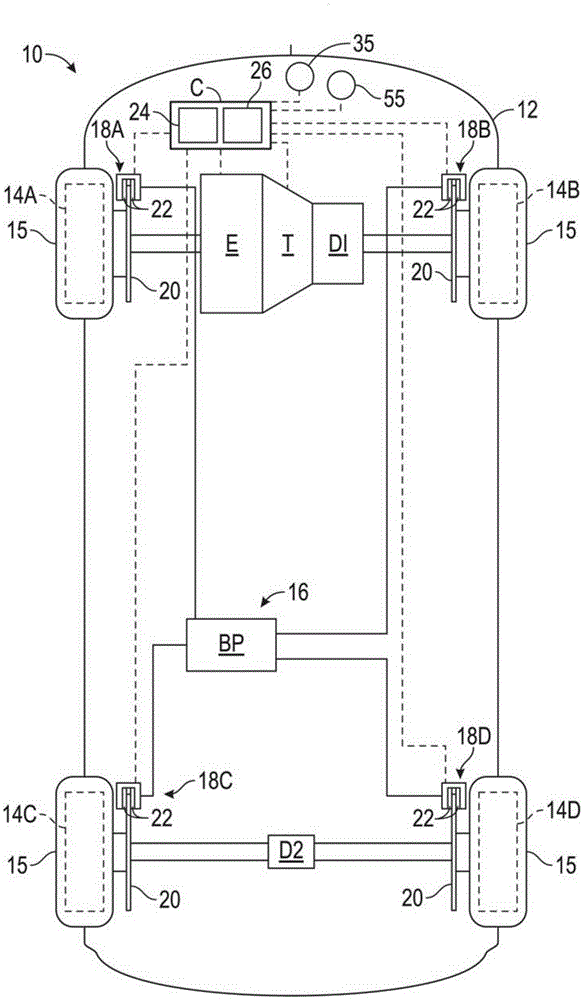
[0065] Referring to the drawings, wherein like reference numerals refer to like parts throughout, figure 1 Vehicle 10 is shown which may have a body 12 operably connected to rotatable wheels 14A, 14B, 14C, 14D for moving body 12 when the vehicle is propelled by engine E via transmission T. In one non-limiting example, vehicle 10 is a front wheel drive vehicle. As is known, differential case D1 is operatively connected to the front wheels 14A, 14B, while differential case D2 is operatively connected to the rear wheels 14C, 14D via half shafts. Tires 15 are shown mounted on wheels 14A, 14B, 14C, 14D. The vehicle 10 includes a braking system 16 configured to stop rotation of the wheels 14A, 14B, 14C, 14D. The braking system 16 includes a fluid pressure source BP in communication with a corresponding braking mechanism 18A, 18B, 18C, 18D operatively connected to each corresponding wheel 14A, 14B, 14C, 14D. The brake mechanisms 18A, 18B, 18C, 18D each have a brake rotor 20 rotata...


PUM


Abstract

A method of estimating brake pad wear includes determining required braking energy to be dissipated by a braking system as a fraction of total kinetic energy according to an energy partitioning model. The required braking energy is distributed to vehicle braking mechanisms according to a vehicle dynamics model. Rotor temperature of each brake rotor may be determined according to a rotor temperature model that utilizes the required braking energy and the distribution of the required braking energy, and determining brake pad wear of each brake pad according to a brake pad wear model that utilizes the rotor temperature and the distributed required braking energy. A first brake pad wear model is implemented under first operating conditions, and a second brake pad wear model under second operating conditions. The brake pad wear is indicated via a brake pad wear indicator output device. A vehicle has a controller that implements the method.

Description

technical field [0001] The present teachings generally include a method of estimating brake pad wear and a vehicle having a controller implementing the method. Background technique [0002] Brake pad life testing has been implemented on vehicles in a number of ways. Some vehicles have a mechanical sensor that provides an audible sound that contacts the brake rotor when brake pad wear is evident. Some vehicles have an electronic sensor that provides a single signal when the brake pad wear reaches a predetermined amount of wear, and the electronic sensor indicates this signal to the vehicle operator as a message in a vehicle information center accessible on the dashboard or steering wheel. Percentage of brake pad life remaining. More advanced wear life algorithms estimate brake pad wear based on estimated rotor temperatures associated with typical driving conditions required for relatively low braking energy. [0003] Certain vehicle owners occasionally or routinely exhibit...

Claims


Application Information

Patent Timeline
Patent Type & Authority Applications(China)
IPC IPC(8): B60T17/22F16D66/02
CPCB60T17/22F16D66/02F16D66/026F16D66/027F16D2066/001F16D2066/006B60Q1/00
Inventor D.B.安塔奈蒂斯M.T.里非
Owner GM GLOBAL TECH OPERATIONS LLC
Why Eureka
Try Eureka